
USING THE µKENBAK-1
Much of this text is from Mark Wilson’s original documentation for his “Kenbak-uino” project from 2011.
Introduction
 Not long after discovering the Arduino it seemed to me it could be a fun project to re-create an early computer, one with just LEDs and switches. I looked at things like the Altair 8800 (1975) but it has 30+ LEDs and 20+ switches and seemed like too much work.
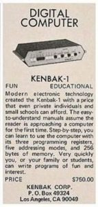
Then I stumbled on the Kenbak-1 (1971). Perfect! Only a dozen LEDs and 17switches. As a bonus it was the 40th anniversary of its introduction. I found a reasonable amount of information online, starting at the Wikipedia article: http://en.wikipedia.org/wiki/Kenbak-1.
This is a software emulation of the Kenbak-1's CPU, and method of operation, together with a basic recreation of the hardware.
Operation
The basic operation is to enter values with the 8-bit switches on the left. CLR clears them all. The bits toggle by default. Pressing (ADDR) SET sets the address register to the displayed value. Pressing STOR writes the displayed value into the memory at the address and increments the address.
In this way programs can be entered. The KENBAK has only 256 bytes of memory and no registers as such (location 0 is A, location 4 is the program counter, etc). DISP displays the current address. READ reads the memory at the address. START starts the program running, STOP halts it.
STOP+RUN single-steps.
For more details and examples - refer to the original manuals:
Theory of Operation Manual
Programming Reference Manual
Programming Worksheets
Laboratory Exercises Manual
(These manuals were sourced from Grant Stockly's original kenbakkit.com website.)
Extensions
Mark added a few extensions to the basic KENBAK-1 behavior.
Extension: SysInfo Instructions
The KENBAK-1 instruction set includes 3 NOOP (no-operation) op-codes: 02Q0, 03Q0 and 031R+[Second Byte] (Q=0..7, R=3..7). I've chosen a particular value of the latter, 0360, to implement an "operating system" SysInfo extension rather than no-operation. (I use 0300 when a real NOOP is required.) The execution of any of the NOOPs is handled by the virtual method
virtual bool OnNOOPExtension(byte Op);
on the CPU class. On the base class it does nothing (just returns true to indicate execution can continue). On the Sketch's derived ExtendedCPU class it traps the 0360 NOOP and execute the SysInfo function as follows:
The value in the A register sets the operation: if the high bit is set, the operation is a "write" otherwise it is a "read". The remaining 7 bits provide the Index of the item. The argument for a write comes from the B register.
The result of a read is placed in the B register.
Note that some writes actually perform an *action* and the corresponding reads do nothing. Executing the SysInfo instruction resets the CPU speed.
The first 8 values for the Index read/write the DS3231 RTC registers (see https://datasheets.maximintegrated.com/en/ds/DS3231.pdf).
Numbers are BCD.
000: Seconds (00..59)
001: Minutes (00..59)
002: Hours (00..23) (always 24-hr, no matter how the RTC is configured)
003: Day (01..07)
004: Date (01..31)
005: Month (01..12)
006: Year (00..99)
007: Control
No validation is performed.
The next 8 values read/write bytes to the subsequent 8 bytes of "user" RAM in the DS3231:
010: Flags controlling the Kenbak-uino.
Currently only 1, if b0 is set, pressing one of the Data switches *toggles* the bit, otherwise it only sets it (as per the KENBAK-1).
011: EEPROM Page Map
See EEPROM Extension. The value of this byte defines how the 1k of EEPROM is partitioned into 8 pages starting with #0 of 256 bytes. Bits in the Map indicate if subsequent pages should be half the size, a 1 means halve, a 0 leaves the size as-is. The least significant bit applies to page #1 -- if it should be half the size of #0 (i.e. 128 bytes). Thus for example, a Map of 012 creates the following page sizes: 256, 256, 128, 128, 64, 64, 64
000 creates 4 full-size pages (higher pages are ignored): 256, 256, 256, 256
012: User #1
013: User #2
014: User #3
015: User #4
016: User #5
017: User #6
These 6 bytes are available for reading and writing non-volatile values.
The final 6 Index values act as follows:
020: Control LEDs
Reading does nothing. Writing sets the control LEDs as follows:
b0:INP
b1:ADDR
b2:MEM
b3:RUN
The upper 4 bits control the intensity of the RUN LED, 0000 = max brightness (PWM=255), 1111 = min (PWM=16).
021: Random
A read returns are random byte, 0..255 in B. Writing a 0 seeds the random number generator using the time etc. Writing a non-0 value uses that as the seed.
022: Program delay milliseconds
Reading does nothing. Writing delays execution for the given duration.
This is separate from the "CPU Speed" (Extension #7 below.)
023: Serial
Reads or writes a byte from the Serial port (@38400baud)
0177: Reading this special value simply returns 0 in Register A, indicating that extensions are enabled. Writing does nothing.
Extension: Blank
Pressing STOP+CLR (i.e. Press STOP and without releasing it press CLR) turns off all LEDs.
Extension: Erase
Pressing CLR+STOR sets all memory to 0 *except* 03 (P register) which is set to 04. The address register is set to 04, ready to enter a program. The CPU speed (BitN-STOP, Extension below) is set to 0.
Extension: Library
Pressing STOP+BitN loads one of eight pre-defined programs:
N Description
0: Simple counter
1: Pattern
2: Counting Clock
3: BCD Clock
4: Binary Clock
5: Das Blinken Lights (random pattern)
6: Sieve of Eratosthenes
7: Set real time clock
Extension: EEPROM
Pressing BitN+STOR writes program memory to EEPROM at "page N". Pressing BitN+READ reads program memory from EEPROM at page N. The ATmega328 has 1k of EEPROM, by default this is divided into 8 "pages" of various sizes:
N Size
0: 256
1: 256
2: 128
3: 128
4: 64
5: 64
6: 64
7: 64
Program memory is always read from or written to starting at address 000.
Thus Bit7+STOR writes the *first* 64 bytes (addresses 000 through to 077) of program memory to EEPROM address 960. Bit0+READ reads all 256 bytes of program space (addresses 000 through to 0377) from EEPROM address 0. Note that EEPROM memory which has not been written to will be read as 0377 (Unconditional JUMP AND MARK INDIRECT).
Extension: SystemInfo
Pressing STOP+READ executes a SysInfo read. The Index is taken from the Address register, the result is placed in the Output register (0200).
Pressing STOP+STOR executes a SysInfo write. The Index is taken from the Address register (there is no need to set b7), the argument is taken from the Input register (0377).
All SysInfo calls are available programmatically and from the front panel but some make more sense that others (for example Delay from the front panel).
Extension: CPU Speed
Pressing BitN+STOP sets the "CPU speed". It sets the delay in milliseconds added after each CPU cycle, equal to 2^N ms. Thus b0+STOP sets the delay to 1ms. b7+STOP sets it to 128ms. The delay is set to 1 at power on and on CLR+STOR (Extension: Erase above) of if a program executes the SysInfo instruction, 0360.
Programs
--Count (STOP+Bit0):
Simply increments the OUTPUT register. Will be a blur unless slowed-down with BitN+STOP.
--Pattern (STOP+Bit1):
Cylon-style single LED moving left-right-left etc. Will be a blur unless slowed-down with BitN+STOP.
The following three programs are only useful if the DS3231 RTC module is installed.
"Clocks", these use System extensions to try to do something useful with the Kenbak-uino. Note that they all display the time in 12-hour format with no AM-PM indicator:
--Counting Clock (STOP+Bit2):
Alternates between showing the hours and the minutes. The Control LEDs are turned off. The hours are displayed thus
P_ HHH HHH
The number of H's is the hour, plus 6 if P is lit. Thus (where '*' denotes a lit LED & '_' unlit)
-- --* *** is 4 O'Clock
*- --- *** is 9 O'Clock etc
The minutes are displayed thus
B_ MMM MMM
The number of M's is the minutes times 10. If the leftmost lit M is blinking, it means +5 minutes. B is always blinking. Thus (where '!' denotes a blinking LED)
!- --* *** is 40 minutes after the hour
!- --- !** is 25 minutes after the hour
This is the easiest clock to actually read the time.
--BCD Clock (STOP+Bit3):
Scrolls back and forth between showing the hours and the minutes in BCD. The minutes display has the leftmost (b7) LED blinking. The Control LEDs are turned off. Thus
-- --- *-- is 4 O'Clock
-- -*- -*- is 12 O'Clock
!- *-- --* is 21 minutes after the hour
!* -*- *-* is 55 minutes after the hour
--Binary Clock (STOP+Bit4):
Shows the time in binary. The minutes are shown on the Data LEDs with the leftmost (b7) LED blinking. The hours are shown on the Control LEDs. Thus
!- -*- *-* * - - * is 9:21
!- **- *** * * - - is 12:55
--Das Blinken Lights (STOP+Bit5):
Just blinks all the LEDs, old-school.
--Sieve (STOP+Bit6):
Builds a table of the odd numbers up to 255 and applies the Sieve of Eratosthenes to them. Then display the primes, HALTing after each one (hit START to proceed to the next one).
--Set Clock (STOP+Bit7):
The DS1307 RTC module has a battery backup that is expected to last up to 10 years, but the clock will need to be set initially, and updated periodically. The hours (BCD, 24-hour format) are in A, the minutes (BCD) are in B.
Step-by-step, here’s how to set the clock:
STOP+Bit7 to load the set clock programs.
CLEAR
SET (set the address to 000)
Enter hours (24 hour format) in BCD, for example:
0001 1000 (18 BCD = 6PM)
STORE (save to A)
Enter minutes in BCD, for example:
0101 0100 (54 BCD)
STORE (save to B)
RUN (run the Set Clock program, sets time to 18:54)
Example
Try entering this program into your µKenbak-1:
003 {Set}{Clear}
004 {Store}{Clear}
103 {Store}{Clear}
001 {Store}{Clear}
134 {Store}{Clear}
200 {Store}{Clear}
003 {Store}{Clear}
001 {Store}{Clear}
043 {Store}{Clear}
010 {Store}{Clear}
344 {Store}{Clear}
004 {Store}{Start}
The numbers are octal, and each octal digit is entered as a three-bit binary number. That’s what the numbers under the LEDs are for. For example, the octal number 134 would be entered in the Kenbak-1 as
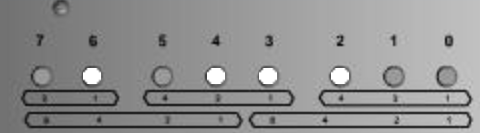
Yeah, programming was hard back then!
If you’re satisfied with blinking lights and a desk accessory that will spark the interest of your friends and coworkers, then you’re done! If you want to learn more, I suggest you check out the scans of the original manuals available above.