These instructions are for the original µKenbak-1 kit. New instructions for the µKenbak-1 in the steel/aluminum case are here.
I would strongly suggest comparing the parts you received with the list below. Let me know if you’re missing anything and I will send a replacement.
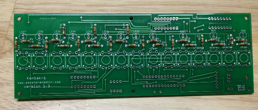
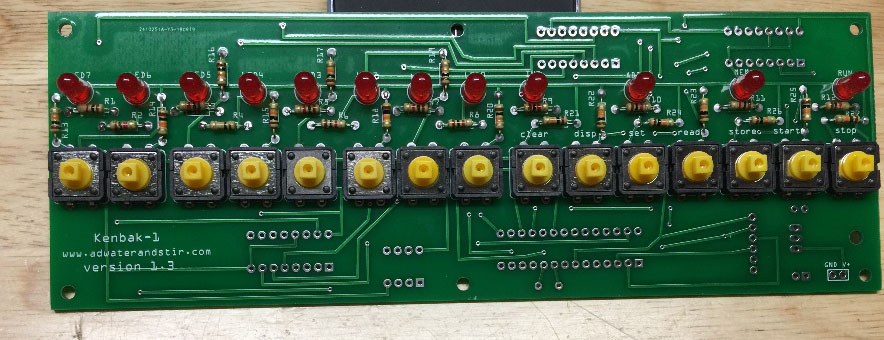
These instructions are for version 1.4 of the µKenbak-1 kit (see the lower left of your circuit board.) If you have version 1.3, you can find instructions here, including instructions to retrofit a real time clock module.
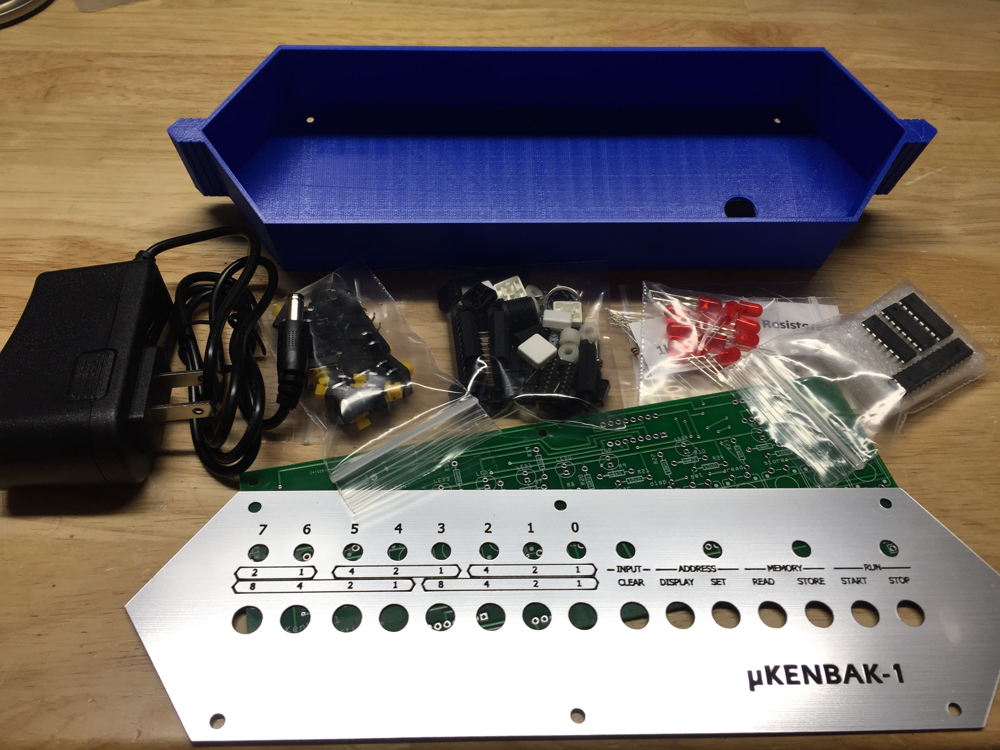
Parts List
- 1 x PC Board
- 1 x Front Panel
- 1 x DC-022 Power jack
- 1 x 9v Power Supply
- 8 x 5mm White (clear) LED
- 4 x 5mm Yellow LED
- 8 x 2.2kΩ Resistor
- 4 x 470Ω Resistor
- 15 x 10kΩ Resistor
- 15 x tactile push button
- 8 x black key caps
- 7 x white key caps
- 1 x 0.33µF Capacitor
- 1 x 0.1µF Capacitor
- 1 x 7805 Regulator
- 6 x 20mm M-F Standoff
- 6 x 14mm Steel Screws
- 6 x 3mm Nylon Nuts
- 6 x Nylon Spacers
- 1 x 16MHz Crystal
- 3 x 16 Pin DIP Socket
- 1 x 28 Pin DIP Socket
- 1 x ATMega328p Microcontroller
- 2 x 74HC165 Shift Register
- 1 x 74HC595 Shift Register
- 1 x Project Box
- 1 x Front Panel
- 1 x DS1307 RTC Module
Other Parts You May Need
- Soldering Iron with a nice fine tip
- Good Solder (I recommend Alpha Fry Rosin Core 0.032” Solder)
- Phillips Screwdriver
- Needle-nose Pliers
- Side Cutters (Nippers)
A word about soldering: Don't underestimate the need for good solder and a good soldering iron. Most problems I've seen people have with this kit are caused by cold joints or insufficient wetting. That doesn't necessarily mean you have to spend a lot of money. I've had good luck with $8 soldering kits from eBay (however I do throw away the solder that comes with those...) Just make sure it has an adjustable temperature and comes with an assortment of tips. Right now I'm using a $55 soldering station and it works great. I strongly advise you to get quality 60/40 Rosin core .032" diameter solder (I use Alpha Fry). The spools I buy are only $10 and well worth it. I set my iron to 400 degrees and use the fine point tip.
Your ATMega328p will arrive pre-programmed, but you may want to upload the software at some point. You can do that by following the instructions on this page.
- Start off by finding the bag labeled “2.2kΩ and 470Ω Resistors”.
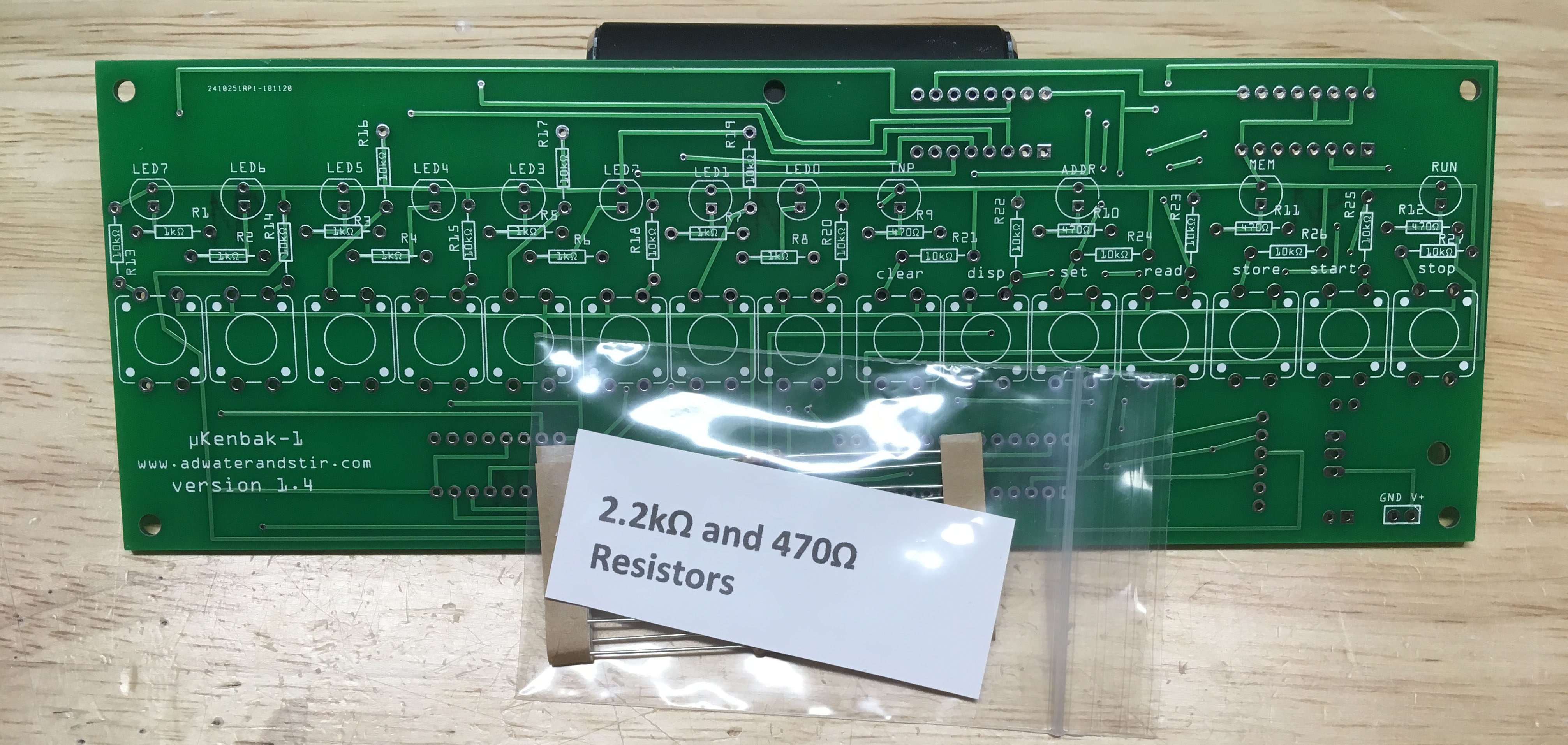
- Add the 8 2.2kΩ resistors where the board says 1kΩ resistors (I increased the value of the resistors to reduce the LED brightness) in locations R1 to R8. Place the 470Ω resistors where labeled in positions R9 to R12. Resistors are non-polarized, meaning they can go in either direction, you do not need to worry about orientation.
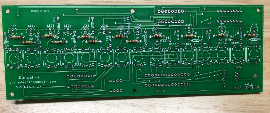
- Next is the bag labeled “10kΩ Resistor”.

- Add the 15 10kΩ resistors to locations R13-R27.
- Next is the bag of 12 LEDs.

- The white LEDs are in LED0 to LED7 positions, the yellow LEDs are for the four LEDs on the right side.
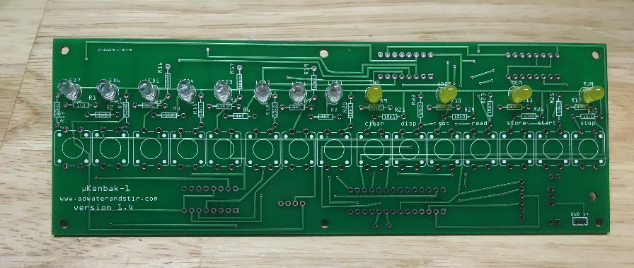
- The orientation if the LEDs is crucial. Make sure the long lead of the LED is toward the bottom of the PC board and the flat side of the LED is toward the top.
- The LEDs should fit snug up against the circuit board.
- Grab the ziplock bag of 15 tactile button switches.
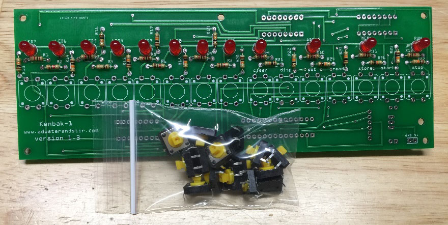
- Orientation of the switches does not matter, so solder them onto the PC board.
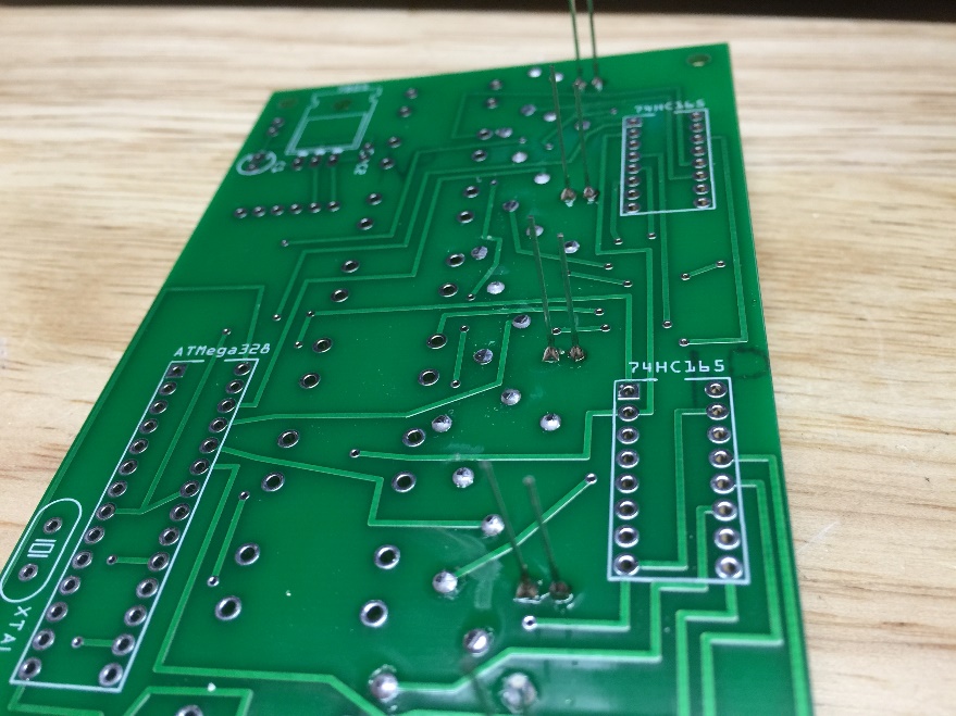
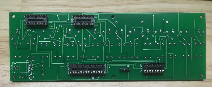
- Next is the bag of assorted parts.
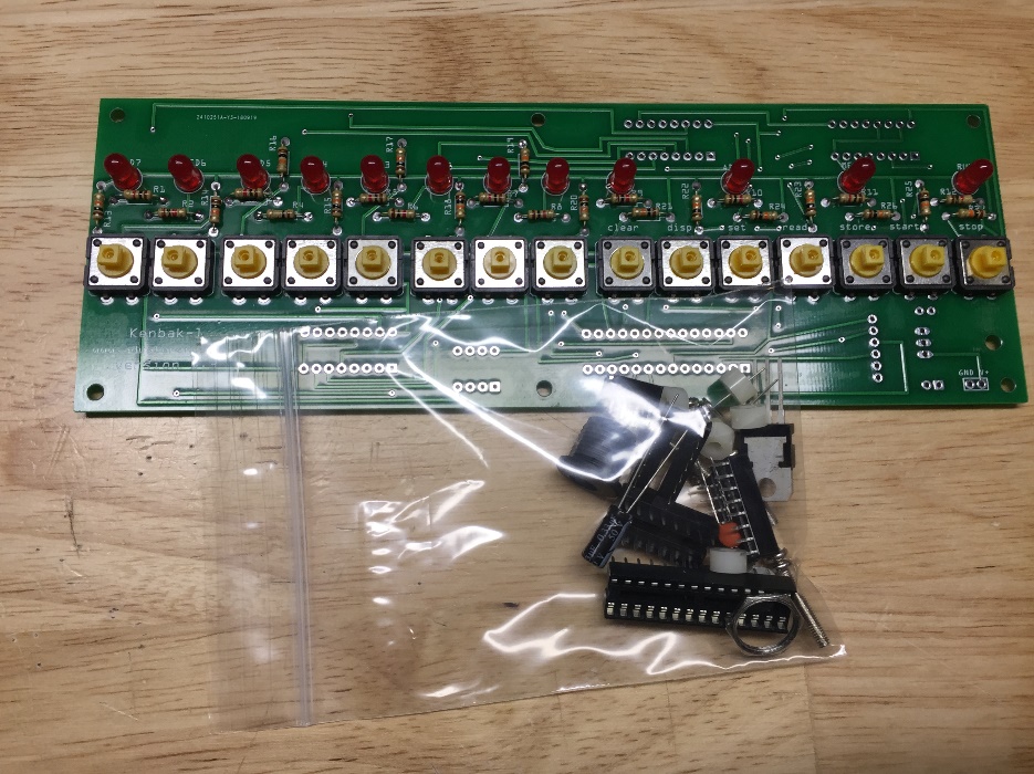
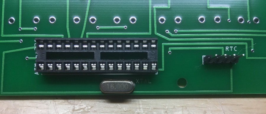
- Turn the board over and you will see clearly marked the locations for the DIP sockets. Make sure the “notch” is oriented in the same location shown in the socket outline on the PC board.

- Solder the DIP sockets and four-pin male header into place.
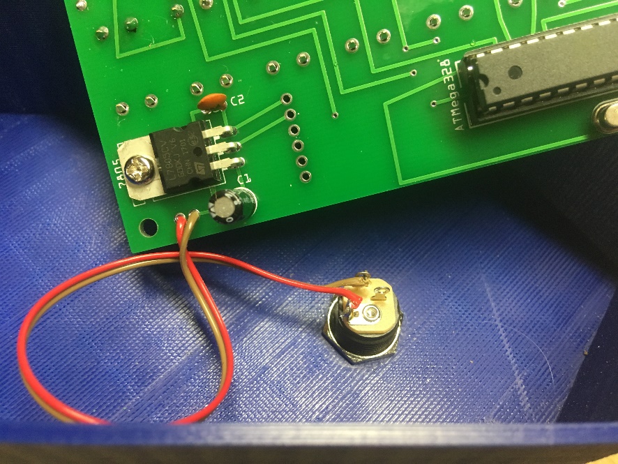
- Next place the 7805 regulator on the board as pictured. It’s not necessary, but you can bend the leads at a 90 degree angle.
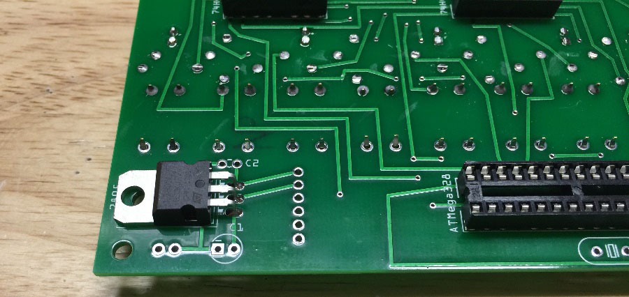
- Get the two capacitors. The ceramic capacitor goes in C2 – it does not matter which way it faces.
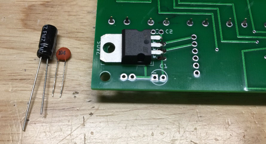
- However, the electrolytic capacitor (C1) must have the short lead in the hole marked with a “-“sign. That lead is also marked on the side of the capacitor.

- Solder the crystal under the socket where the board says “XTAL”. Orientation is not important.
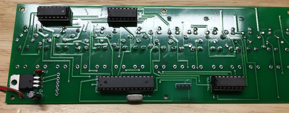
- Next you will place the four integrated circuits in their sockets.
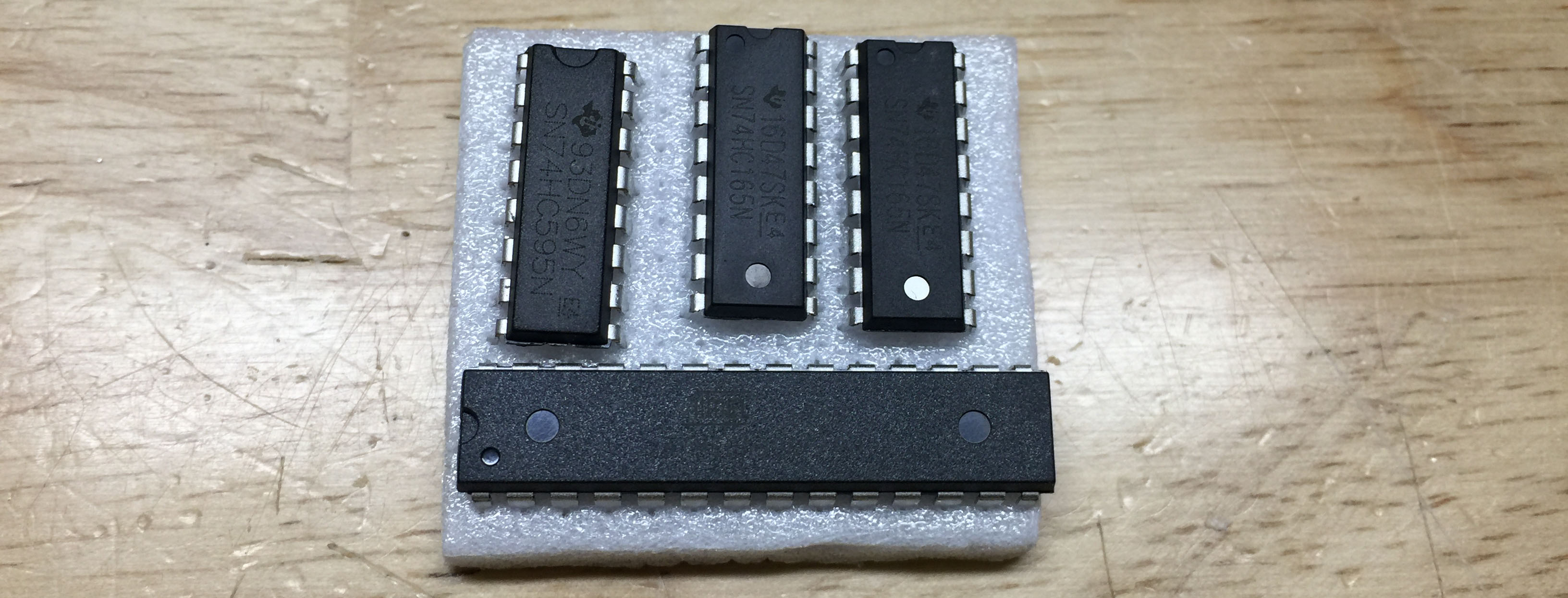
- Make sure they are oriented correctly – the notch on the end of the chip will be next to the label printed on the PC board. Be sure the correct chip is in the correct labeled location.
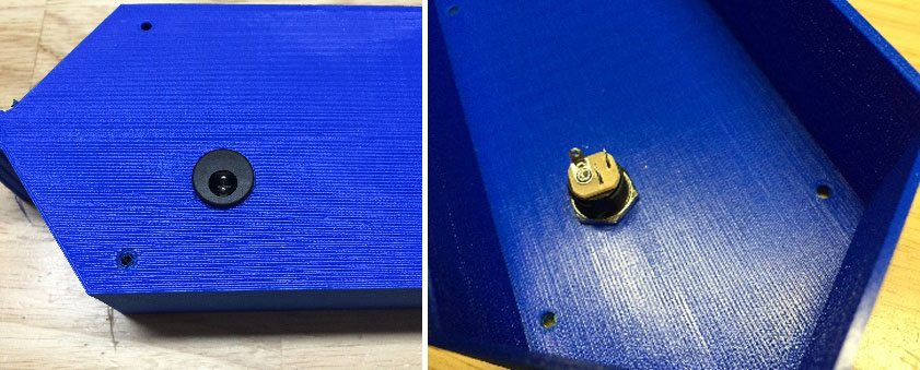
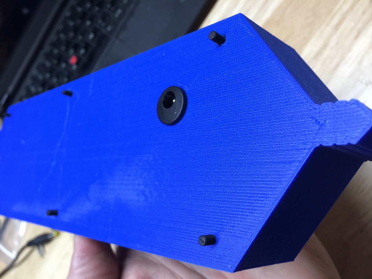
- Put the DC power connector in the rear of the case and secure it with the nut.
- Note: There is now a new RTC module included with the kit. This module is based on the DS3231 chip which is much more accurate than the RTC module originally included with this kit. The next two steps are different than the instruction booklet included with the kit.
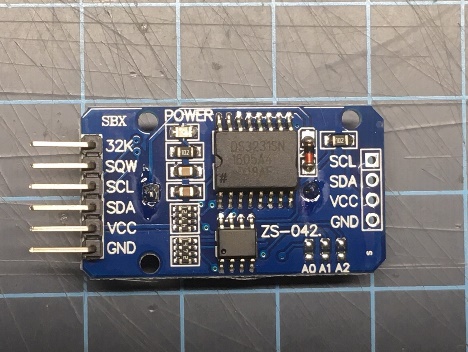
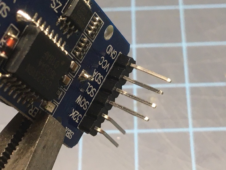
- You will first need to gently straighten the SCL, SDA, VCC, and GND pins (leave the 32K and SQW pins alone, they are not used.)
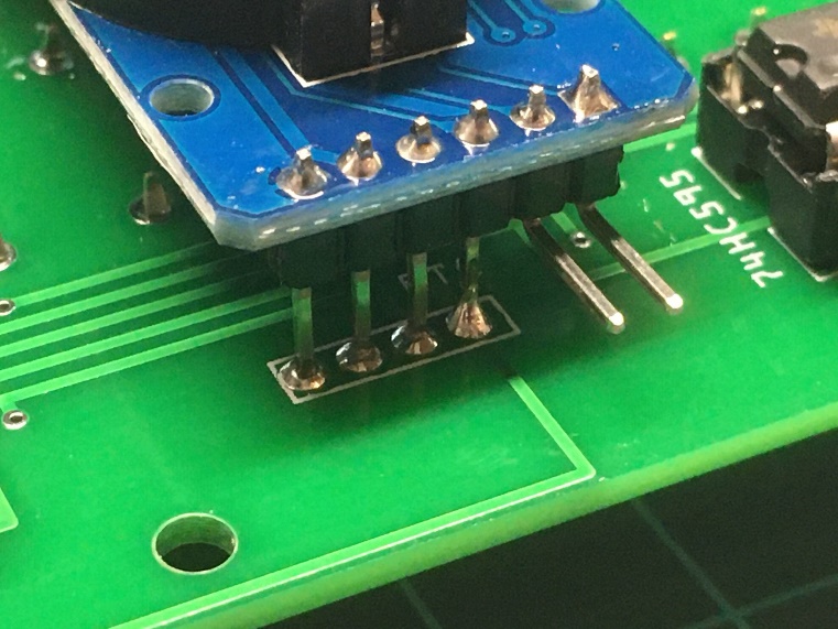
- Insert the CR2032 battery in the module and solder it to the circuit board as shown. Be sure to leave clearance below the RTC module – you will have to hold it in place while you solder the first connection, or place something underneath temporarily while you solder. Make sure there are no electrical shorts below the module.
- Solder wires from the DC jack to the PC board, minding the polarity.
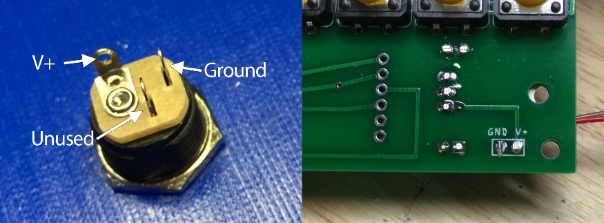
- The power leads do not have to be too long, but make sure they're long enough to allow you to continue to work on the front panel.
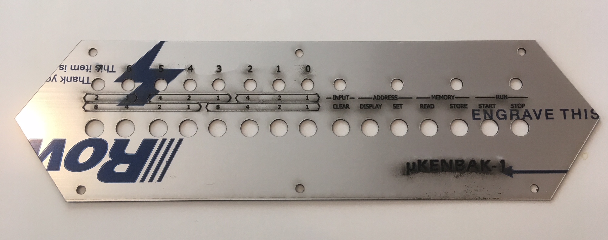
- Next we’ll add the front panel components.
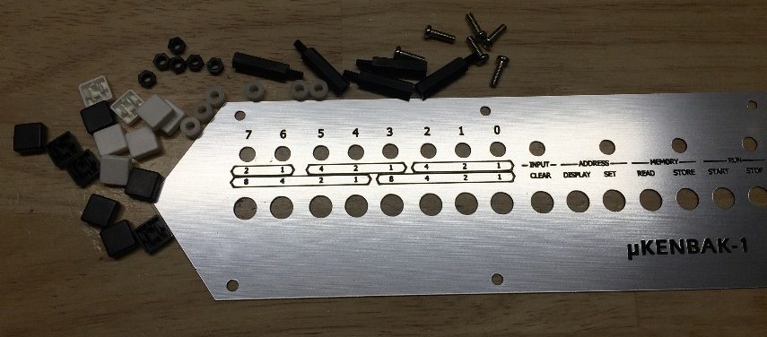
- Your font panel may have arrived with protective film over it. It will peel away easily, but you will need to use the back of your fingernail to gently scrape away the small pieces of plastic that will remain inside the letters and numbers like “0”, “8”, “4”, “D”, “R”, etc. This will just take a couple minutes.
- Turn the front panel over, put the six steel bolts in the holes, and place the nylon spacers on the bolts as shown.
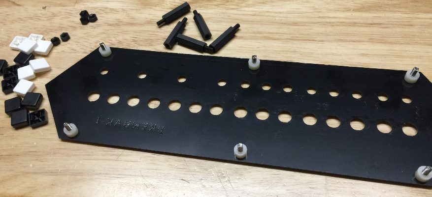
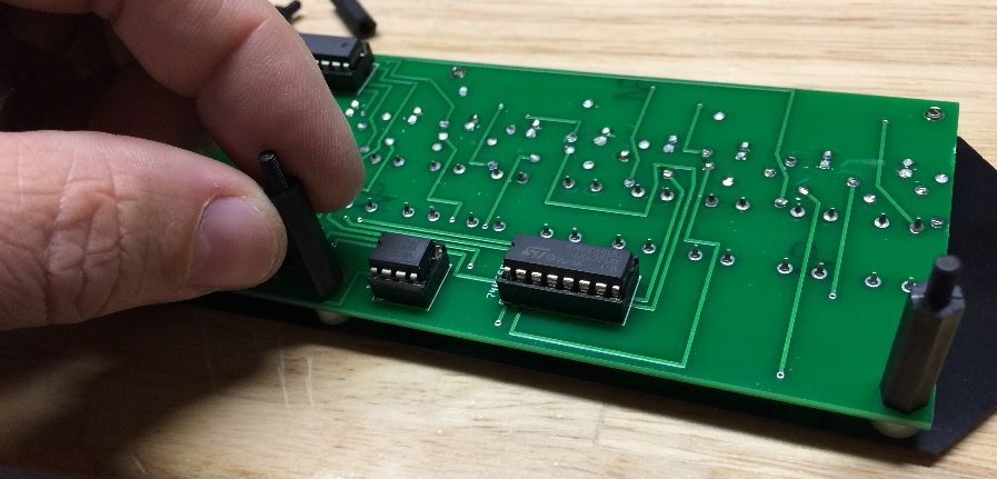
- Put the PC board in place, aligned with the bolts.

Screw the nylon standoffs on the bolts.
Here's a tip: don't completely tighten the bolts to the standoffs, it may cause the front panel to pucker. Leave a little bit of "play" for the front panel to find its own location.
- You can now place the front panel assembly into the case, aligning the nylon standoffs with the holes in the case. If they don’t easily go through the holes, you can enlarge the holes with a 3mm or 1/8” drill bit. Add the nylon nuts to secure the case and front panel.
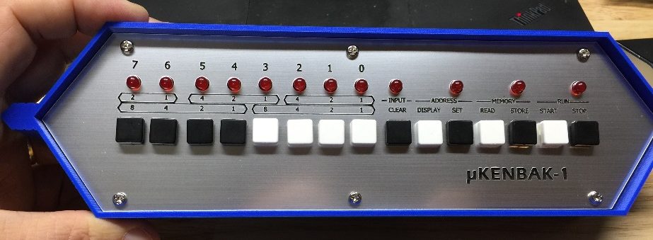
- The button caps will snap into place. See the photo below for the proper location of the black/white caps.
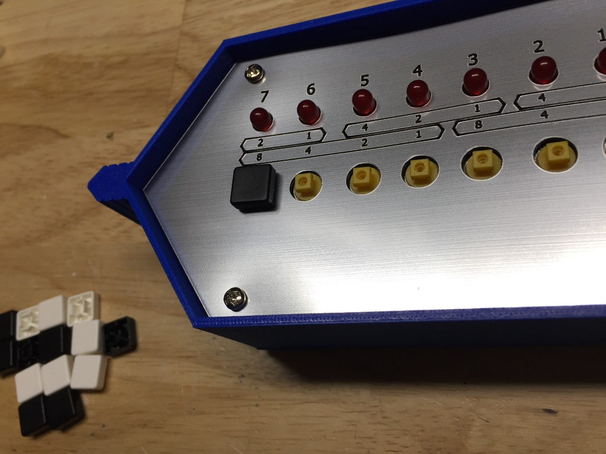
CONGRATULATIONS! YOUR µKENBAK-1 IS COMPLETE!
- Power it up and let’s see how it works!