- These are the instructions to convert your version 1.4 kit (in bamboo case) to a kit in an acrylic case with I/O expansion board, including VT100 emulator.
Note: The upgrade kit is no longer available to purchase. These instructions are here for those that have previously purchased the upgrade kit.
These instructions are specifically to convert a version 1.4 main circuit board to use the I/O expansion.
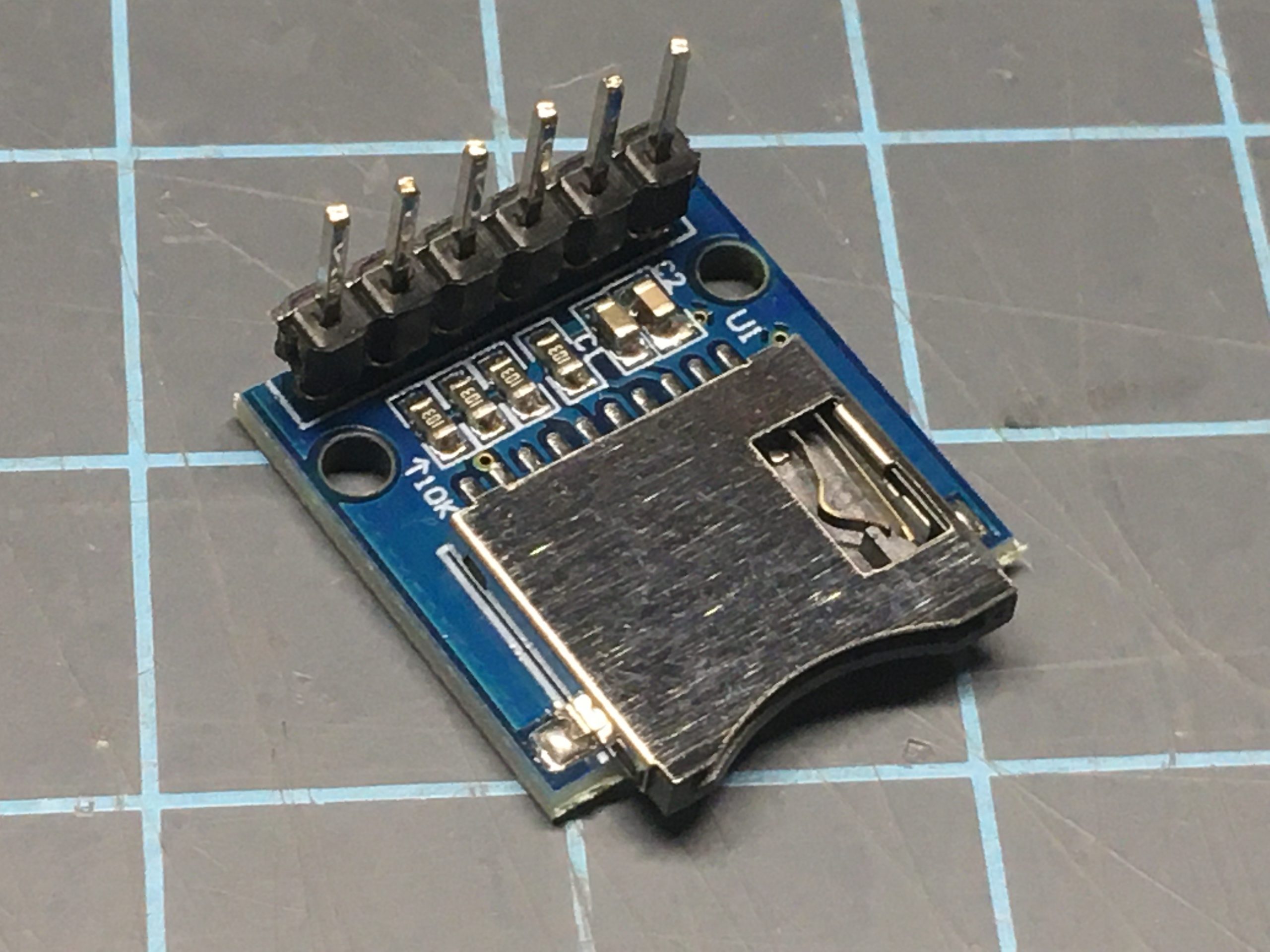
- If you received a micro SD card module with unattached header pins, you will need to solder them with the header pins coming out of the top of the module.

- This may seem to be the non-intuitive location for the header, but it is correct for this kit.
Depending on the age of your Arduino, you will probably want to update the software. You can find the instructions at this link.
You should install the latest disk images and settings profiles to your SD card. You can download those here.
Once you have everything buttoned up, you will no doubt want to try out the VT100 emulators with your Altair-Duino. Click here to see instructions and a video.
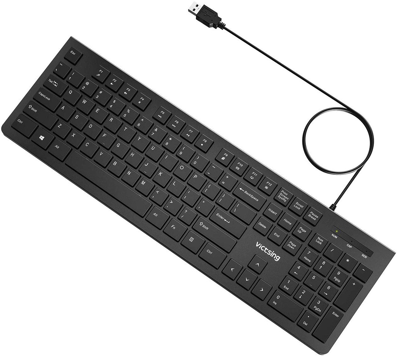
- Any standard wired USB keyboard should work, but you need to avoid using a keyboard with a USB hub. Some keyboards have built-in USB hubs and those will not work either. If your keyboard has one or more USB sockets on it (to connect a mouse for example), or is wireless, then it likely contains a USB hub and will not work.
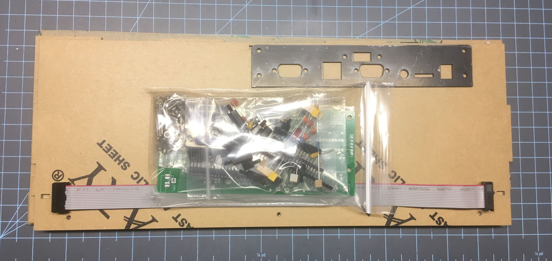
The build of the new I/O board will be slightly different - there are now only two 4.7k resistors (instead of four) and the relocation of the USB connector.
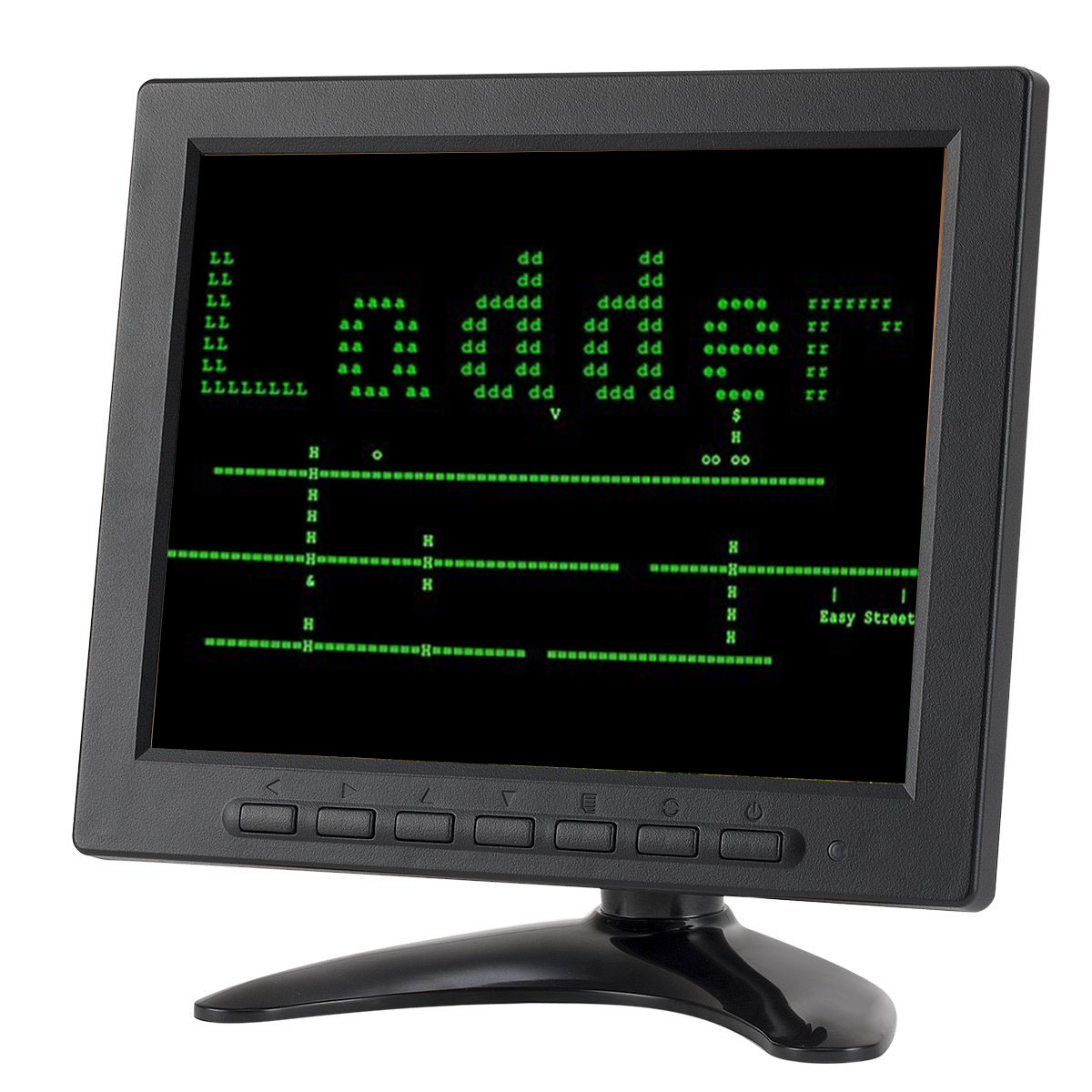
I also like this LSLYA 8 inch TFT LCD Security Monitor. It's small, light, and inexpensive (about $64) and it has a variety of inputs, including VGA, HDMI, composite, and component. Everything you need for almost all retro computing possibilities. Plus it has a 4:3 retro computing aspect ratio.
But I don't want to lose my Bluetooth!
You can keep your Blutooth module, but it will require you to flex your DIY muscles! This procedure is completely optional and is only required if you want Bluetooth and the VT100 emulator.
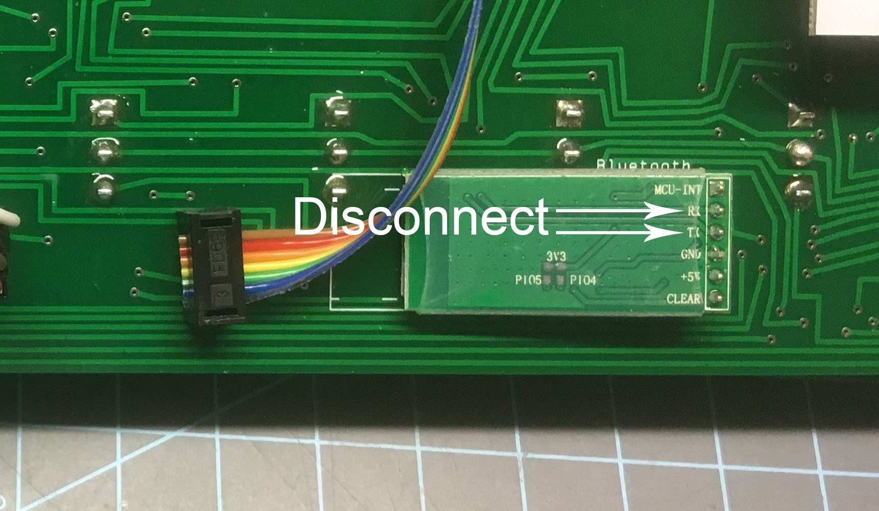
- You will need to disconnect the RX and TX pins from the main circuit board. It may be easier to completely desolder and remove the modules, clip (or desolder) the RX and TX pins, then resolder the Bluetooth module. You can then connect the RX and TX pins directly to the Arduino.
(These instructions are directly from David Hansel's documentation.)
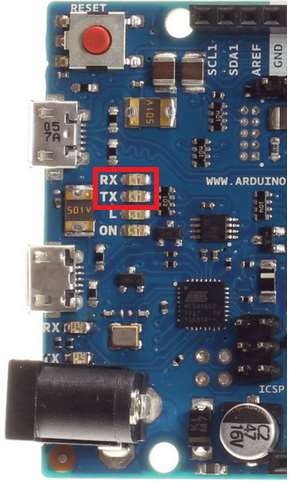
This port is disabled by default since it uses two I/O pins that are not connected to headers on the Arduino Due: the pins controlling the RX and TX LEDs next to the Native USB port (framed in red in the image on the right). These pins are accessible as digital pins 72 (RX) and 73 (TX) on the Arduino Due. Despite their location next to the Native USB port they have no connection to the port and can be freely controlled by software. To add a serial interface using these pins do the following:
(Optional but recommended): remove the RX/TX LEDs. I did try leaving the LEDs in place and just soldered onto the LEDs themselves and serial communication did work. However, the LEDs go to +3.3V through a 1k resistor which could possibly interfere with the serial signals. Your mileage may vary.
Solder wires to the pads on the left side of the LEDs (the side closer to the “RX” and “TX” labels). These will be the RX and TX wires for the serial connection.
In file host_due.h, change
#define USE_SERIAL_ON_RXLTXL 0
to#define USE_SERIAL_ON_RXLTXL 1
and upload the sketch to the Arduino.Connect the RX LED to the TX pin on the Bluetooth module, and TX LED to the RX pin.