
I/O Expansion Kit
$45.00
Out of stock
Description
*This is included with the Altair-duino Pro kit.
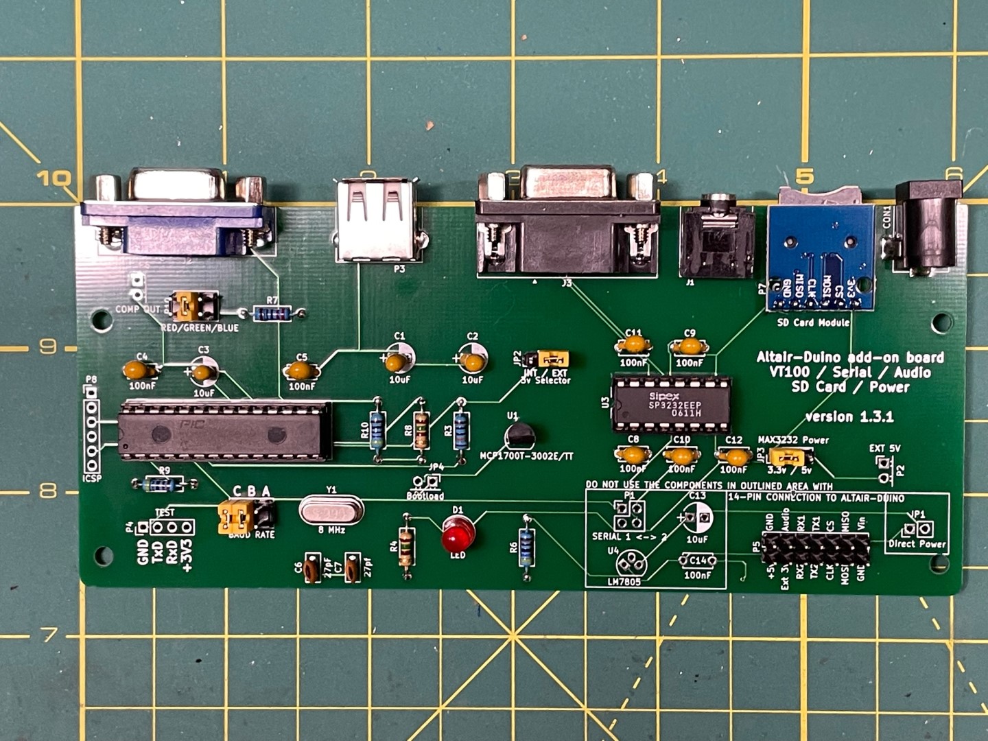
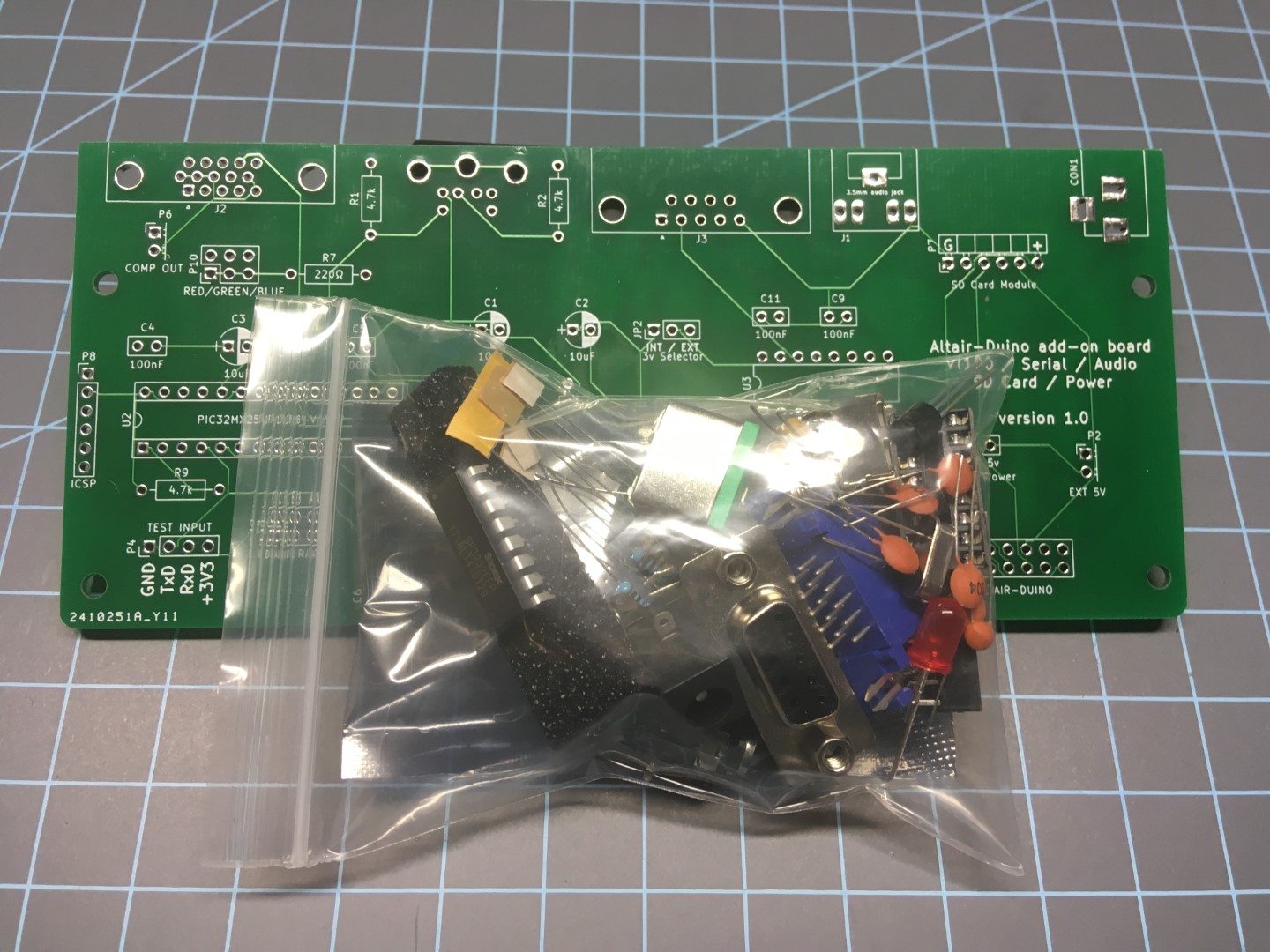
This is the kit for the I/O Expansion normally included with the “Altair-Duino Pro kit“. It includes the custom circuit board, all components, and 9-pin null modem adapter. It will also include the latest I/O Expansion Module Manual.
It can also be used apart from the Altair-Duino. This emulates a VT100 serial terminal using a VGA monitor and USB keyboard. It also has a TTL to RS232 converter. You can configure the board to connect a 9-pin serial device to the VT100 emulator. The new version 1.3 includes an on-board 5v voltage regulator so you can power the board with a standard 9v-12v DC power adapter.
 NOTE: If you are going to use this kit with an Altair-Duino (connected to the 14-pin ribbon cable), you do NOT want to install the 5v regulator and you definitely do not want to jumper JP1 (“Direct Power”). If you do you will likely hear a loud crack and see a puff of smoke… You will also want to include a 14-pin ribbon cable if you don’t already have one.
If you are adding this to the Altair-Duino Standard kit you will want to remove the small daughter card from the Standard kit (that has the power input, SD card module, DB9 connector, etc.) This I/O board takes the place of the Standard kit daughter board.
This was originally designed to be used with the version 1.5 and later Altair-Duino main board. However, it can be used for other purposes by an intrepid maker. If that is you, here are some things you may want to know:
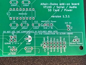
The 14-pin connector “pin-out”:
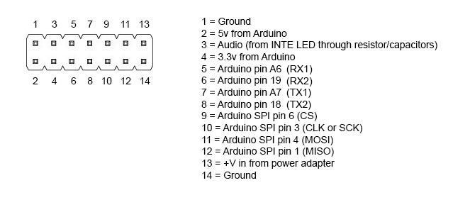 RX1/TX1 (Arduino pins 18/19) are wired to the PIC32 for VT100 emulation.
RX2/TX2 (Arduino pins A6/A7) are wired to the SP3232 for DB9 serial.
The “Test Input” can also be used to provide a connection to the PIC32. All inputs are TTL-voltage compatible.
You can power the board via the USB connector or supply 5v on connector P2. If you provide power to the board through any method other than the Altair-Duino main board, you will want the “3v Selector” jumper set to “INT” (3.3v will then be provided by the MCP1700 voltage regulator.)
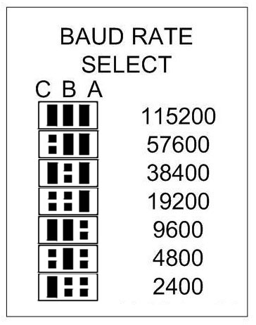
Here are the baud rate settings for the VT100 emulator using the “baud rate” jumpers:
Download the manual (above) for more features of this VT100 emulator.