

Downloadable version of assembly instructions are here.
I would strongly suggest comparing the parts you received with the list below. Let me know if you're missing anything and I will send a replacement.
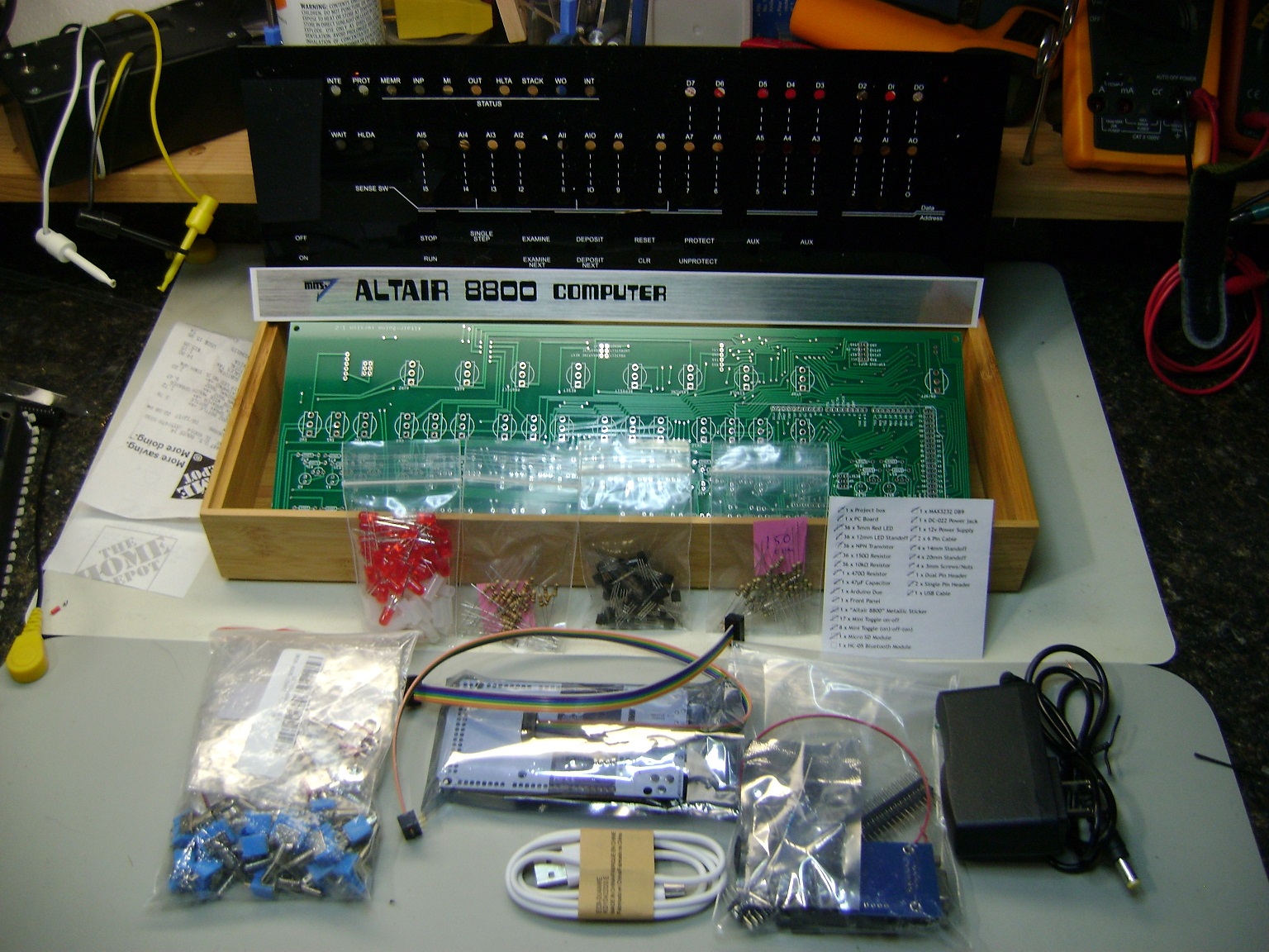
Parts List
- 1 x PC Board
- 36 x 5mm Red LED
- 36 x 12mm LED Standoff
- 36 x NPN Transistor
- 36 x 1kΩ Resistor
- 36 x 10kΩ Resistor
- 17 x Mini Toggle on-off
- 8 x Mini Toggle (on)-off-(on)
- 1 x 470Ω Resistor
- 1 x 47µF Capacitor
- 2 x 1kΩ Resistor
- 2 x 0.1µF Capacitor
- 1 x Pre-programmed Arduino Due
- 1 x Matte Black Screen Printed Front Panel
- 1 x "Altair 8800" Metalic Sticker
- 1 x Bluetooth Module
- 1 x Micro SD Module
- 1 x DC-022 Power jack
- 1 x 9v Power Supply
- 1 x 6 Pin Cable
- 4 x 14mm M-F Standoff
- 2 x 20mm M-F Standoff
- 2 x 20mm F-F Standoff
- 4 x 10mm Nylon Screws
- 2 x M3 Nylon Nuts
- 1 x Dual Pin Header
- 2 x Single Pin Header
- 1 x 6 Pin Female Header
- 1 x 3.5mm Audio Jack
- 1 x USB Cable
- Project Box
- MAX3232 DB9 Serial Module
- 4 pin female-female serial cable
- Laser-cut rear panel
- 30cm Panel Mount USB Extension
- 2 x 8mm Steel screws
- 4 x 10mm Steel screws
- 2 x Steel washers
- 2 x Steel nuts
Other Parts You May Need
- Soldering Iron with a nice fine tip
- Good Solder (I recommend Alpha Fry Rosin Core 0.032” Solder)
- Flat Screwdriver
- Phillips Screwdriver
- Needle-nose Pliers
- Side Cutters (Nippers)
- Drill with 3mm or 1/8" and 12mm or 1/2" bits
- Micro SD Card (256MB is sufficient)
- Computer
A word about soldering: Don't underestimate the need for good solder and a good soldering iron. Most problems I've seen people have with this kit are caused by cold joints or insufficient wetting. That doesn't necessarily mean you have to spend a lot of money. I've had good luck with $8 soldering kits from eBay (however I do throw away the solder that comes with those...) Just make sure it has an adjustable temperature and comes with an assortment of tips. Right now I'm using a $55 soldering station and it works great. I strongly advise you to get quality 60/40 Rosin core .032" diameter solder (I use Alpha Fry). The spools I buy are only $10 and well worth it. I set my iron to 400 degrees and use the fine point tip.
Your Arduino will arrive pre-programmed, but you may have to upload the software at some point. You can do that by following the instructions on this page.
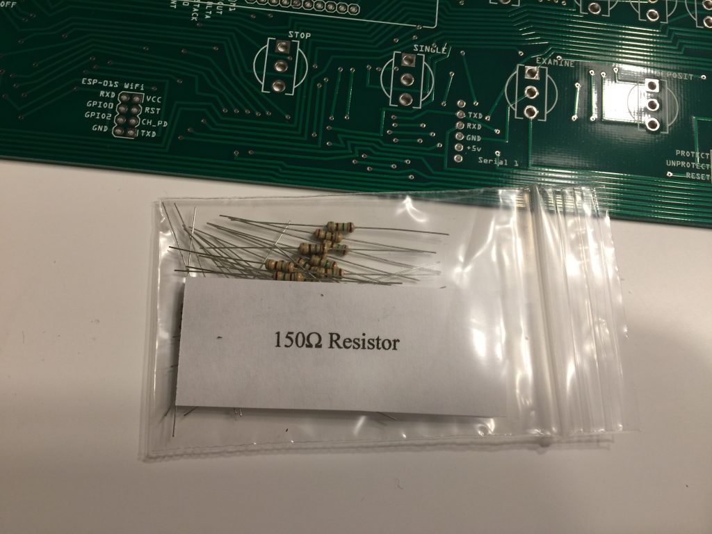
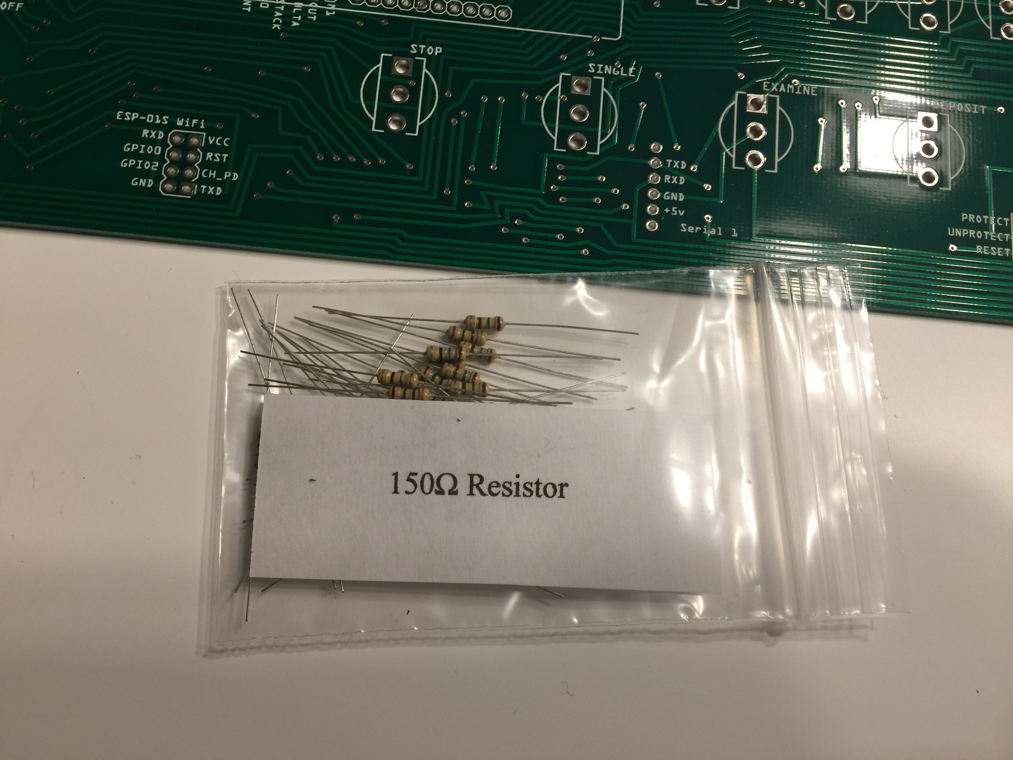
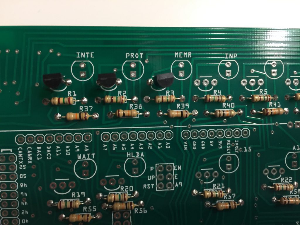
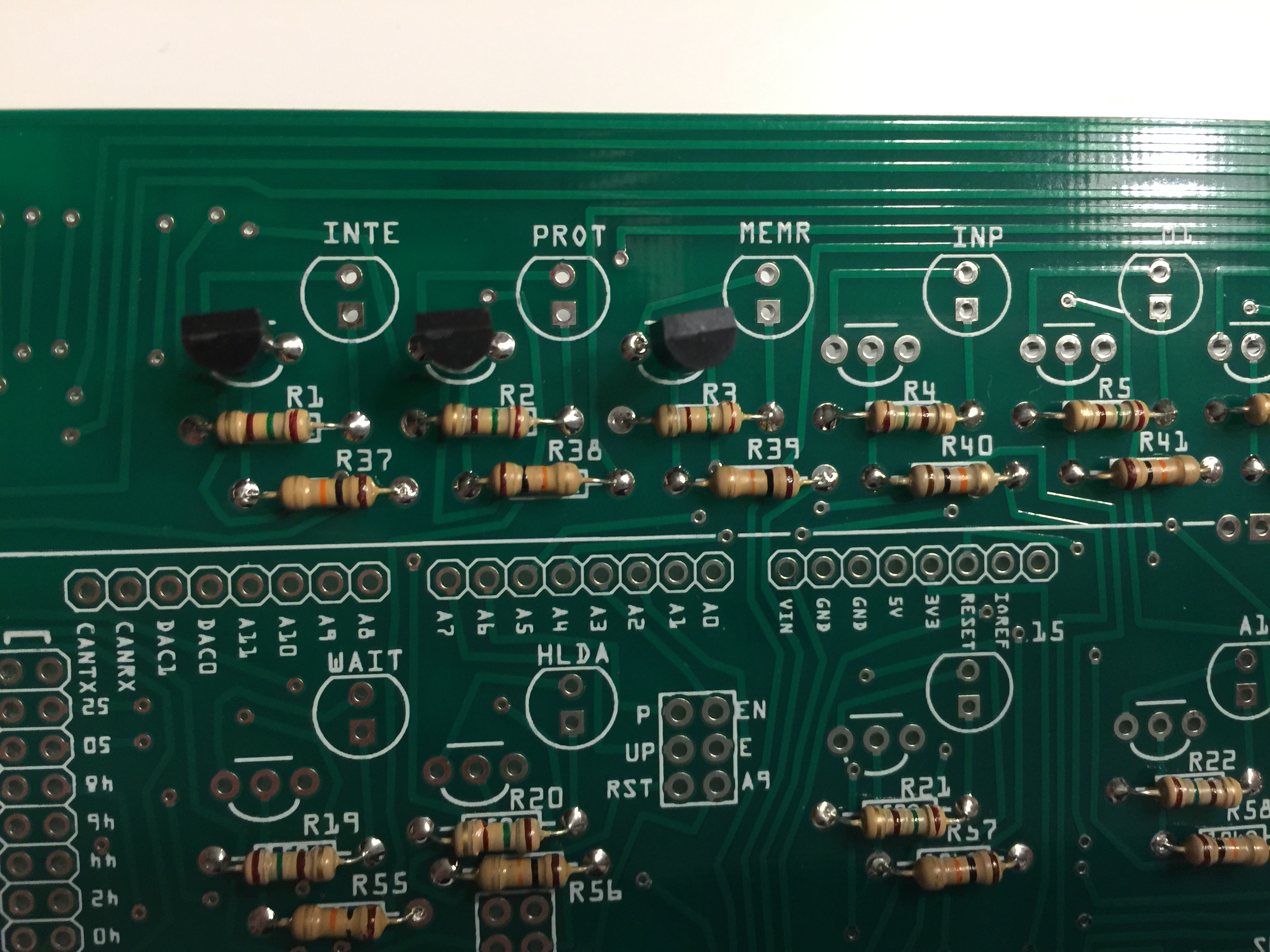
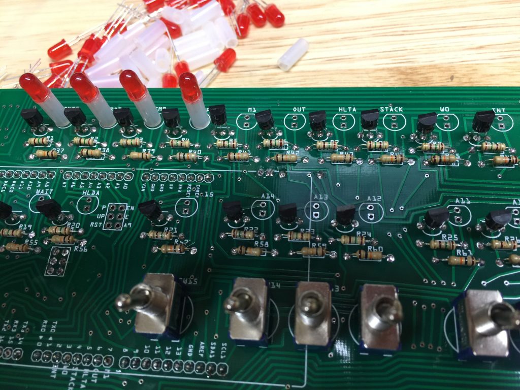
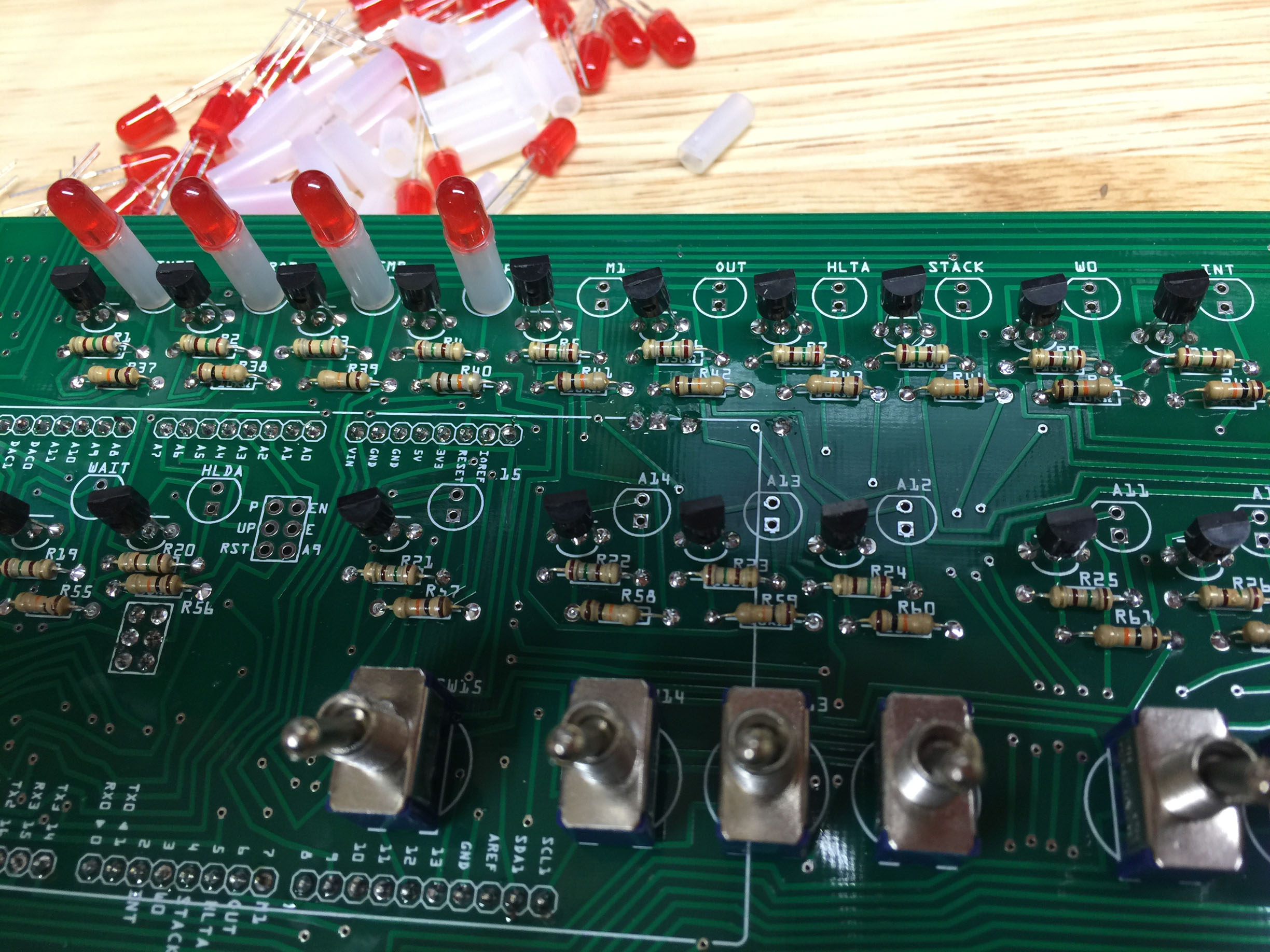
- Start off by finding the bag labeled "1kΩ Resistor". (Your kit has 1kΩ resistors. Previous versions of the kit used 150Ω resistors, but I have found that the LEDs are too efficient and bright for 150Ω resistors.)
- Add the 36 1kΩ resistors to the top rows under the LED/Transistor pairs in locations R1-R36 (where the board is labeled with 150Ω). Resistors are non-polarized, meaning they can go in either direction, you do not need to worry about orientation. Update: Version 1.5 boards are now correctly marked "1kΩ".
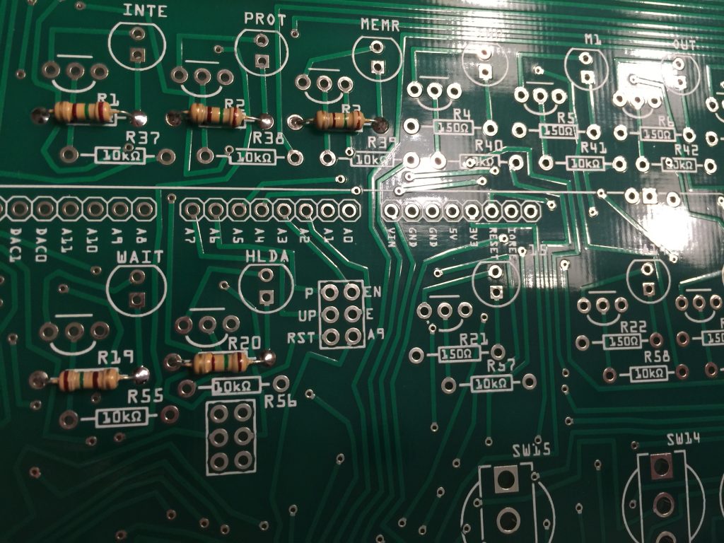

- Next is the bag labeled "10kΩ Resistor".
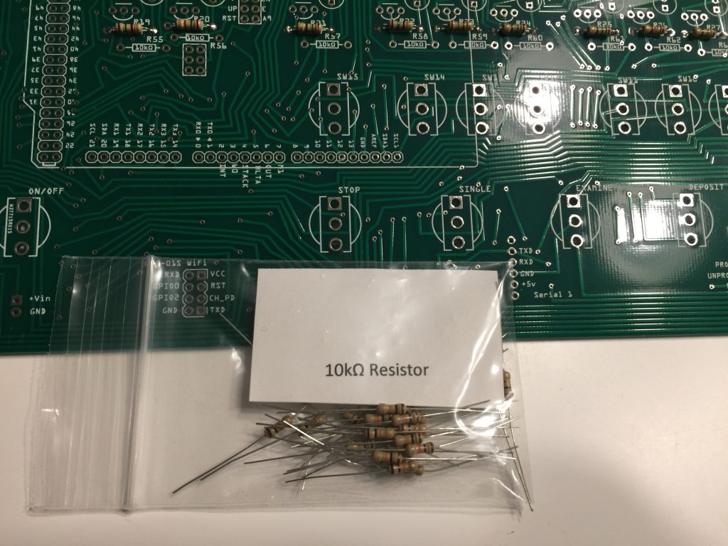

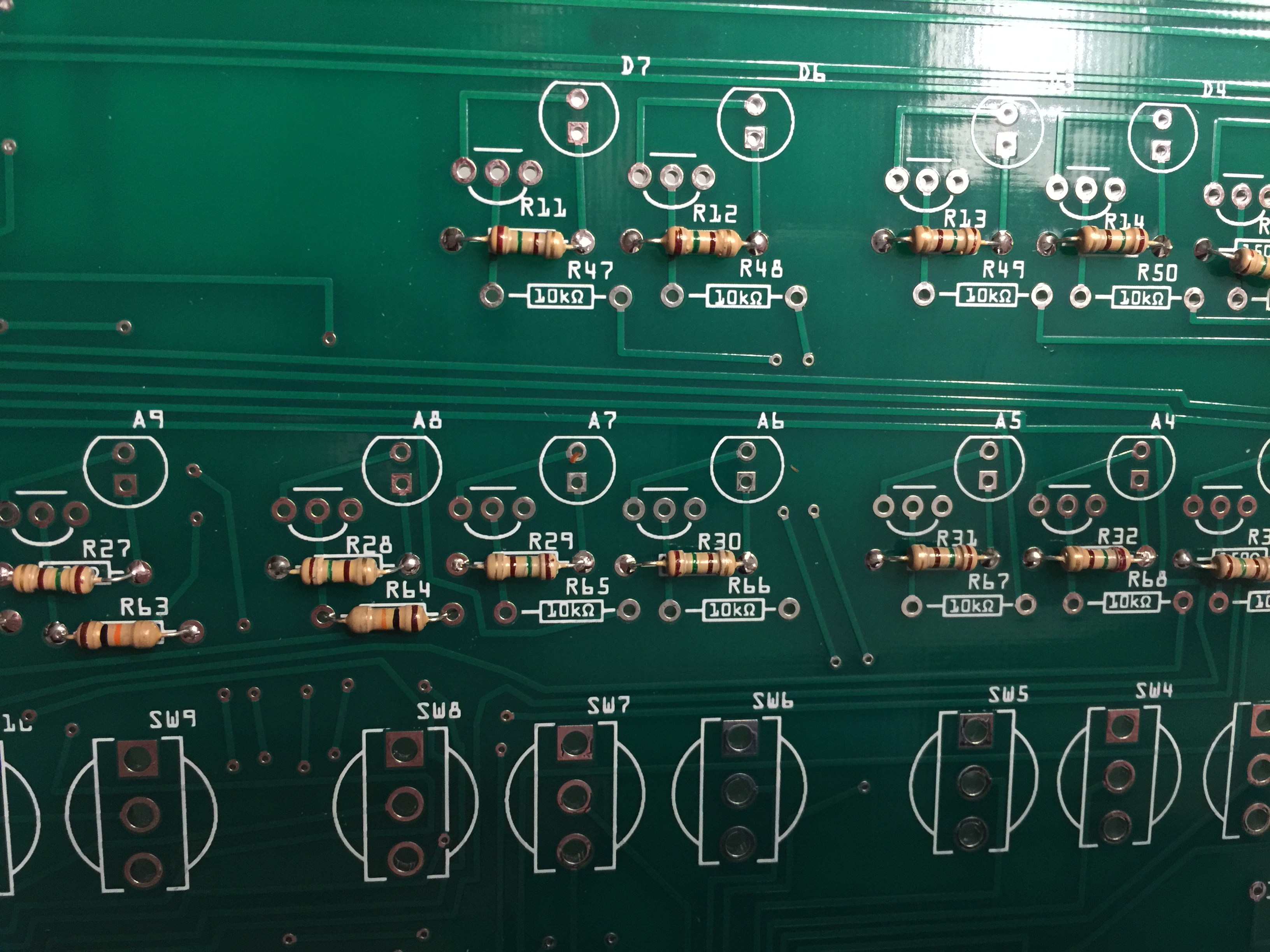
- Add the 36 10kΩ resistors to the second row in locations R37-R72.

- Next is the bag of 36 transistors.
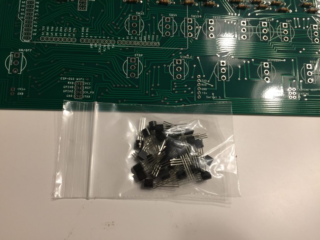
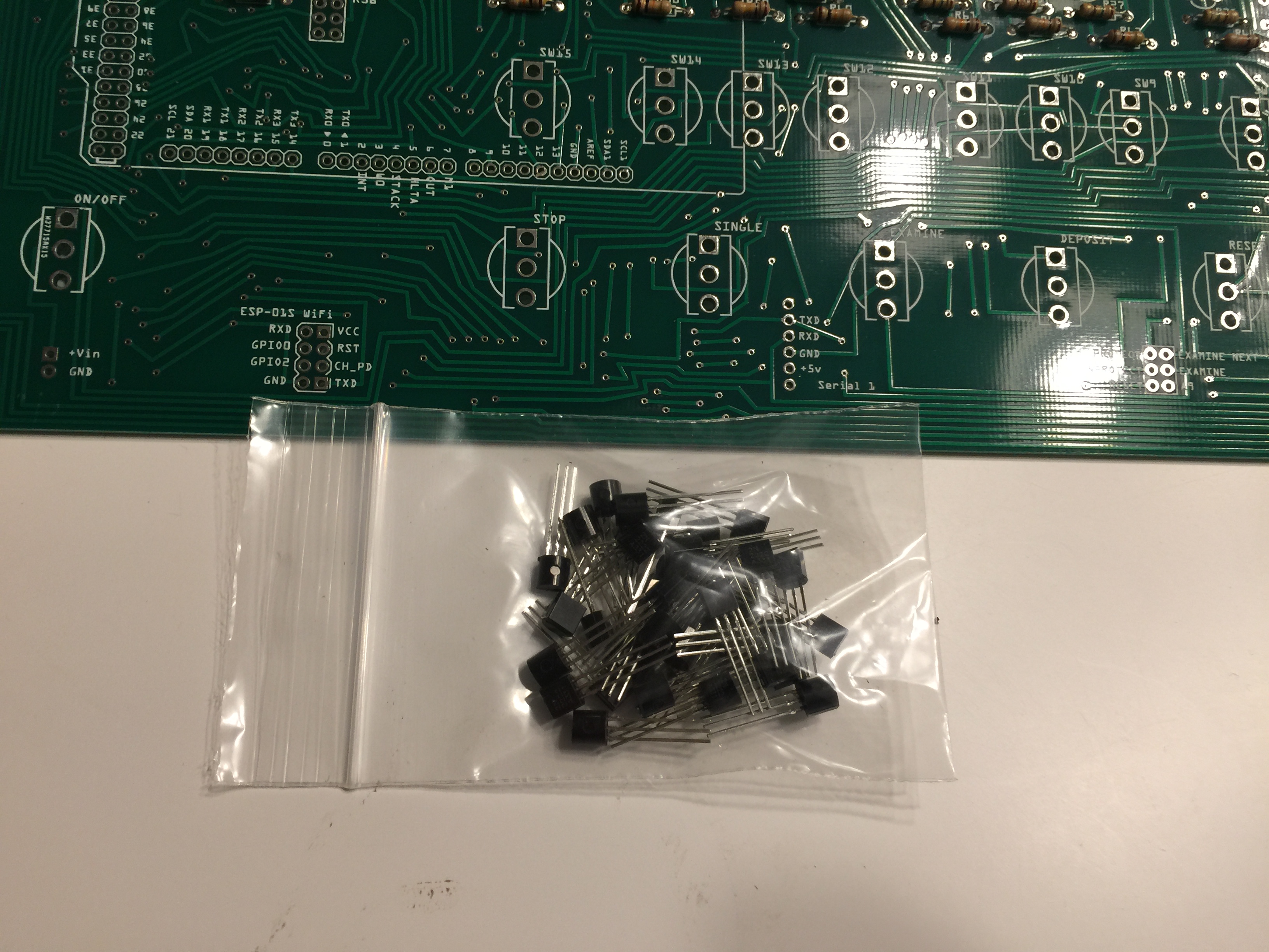
- The orientation of the transistor is crucial, but relatively simple. Just make sure the flat end of the transistor is facing up, just like the image printed on the circuit board.
- Grab the ziplock bag of assorted parts.
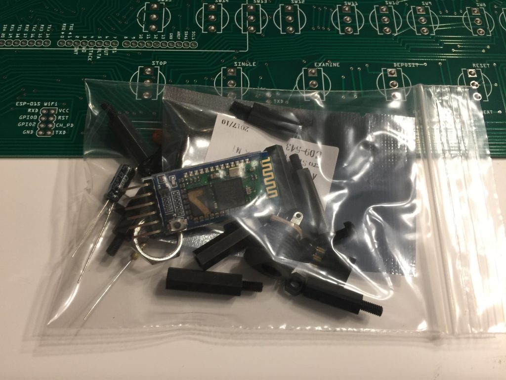

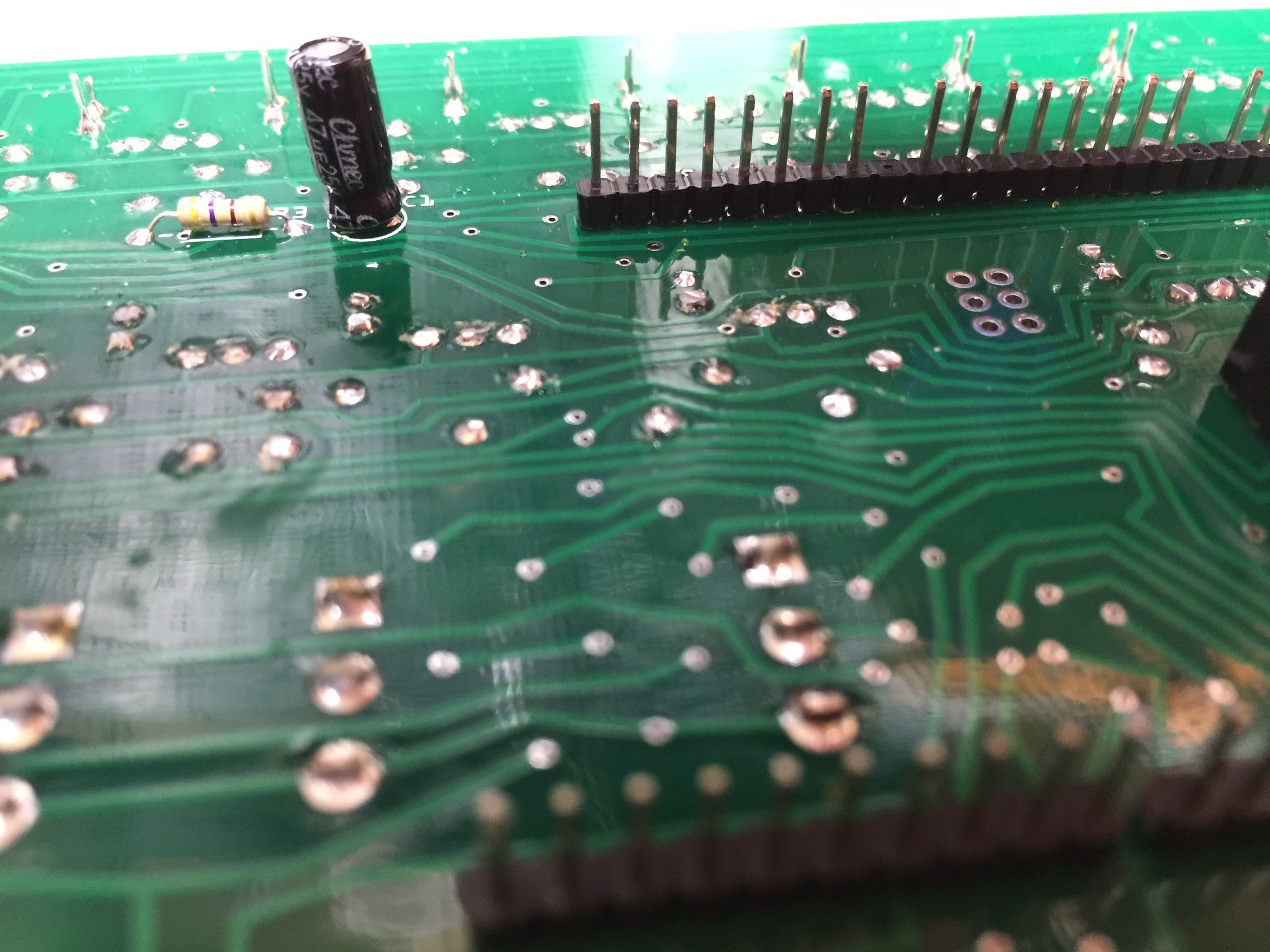
- In that bag you will find one electrolytic capacitor and one 470Ω resistor (Yellow, Violet, Brown, Gold color code). If you don't want to decipher the color code, just know you will find three resistors in the bag, two that match, and one that does not. This is the one that does not match another.
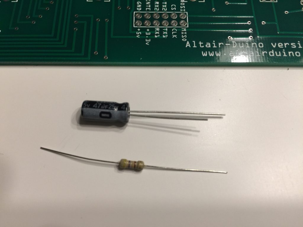
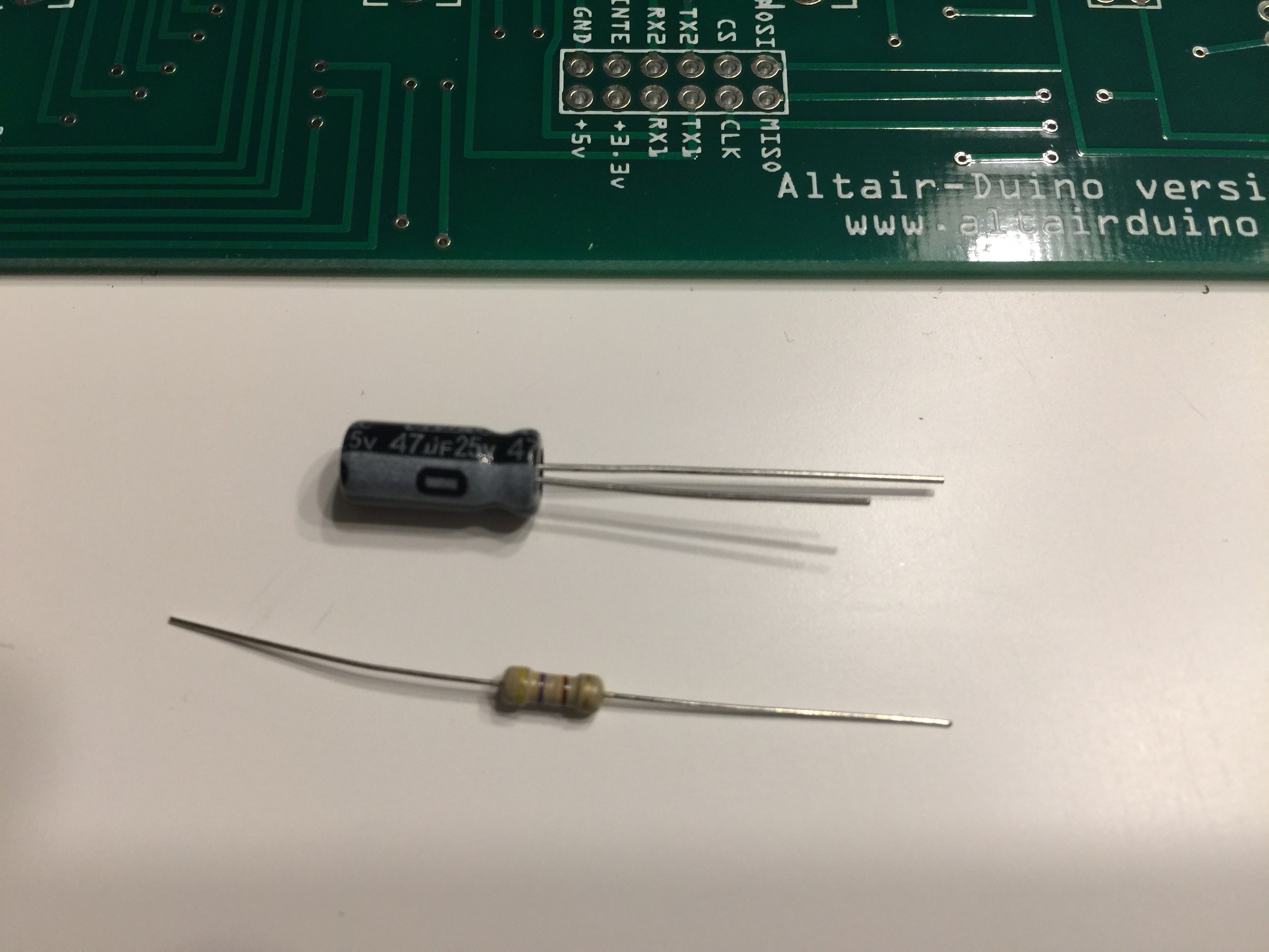
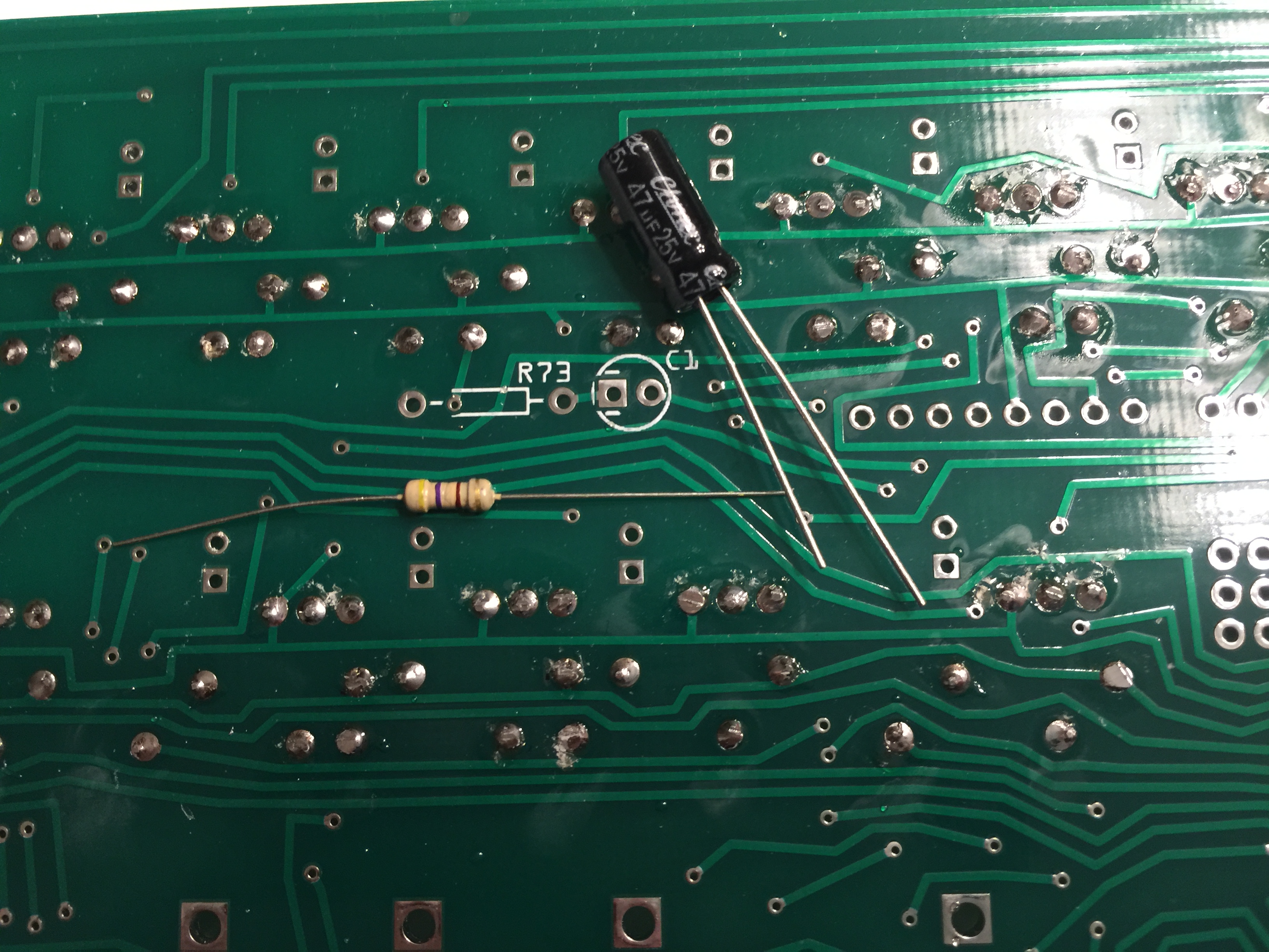
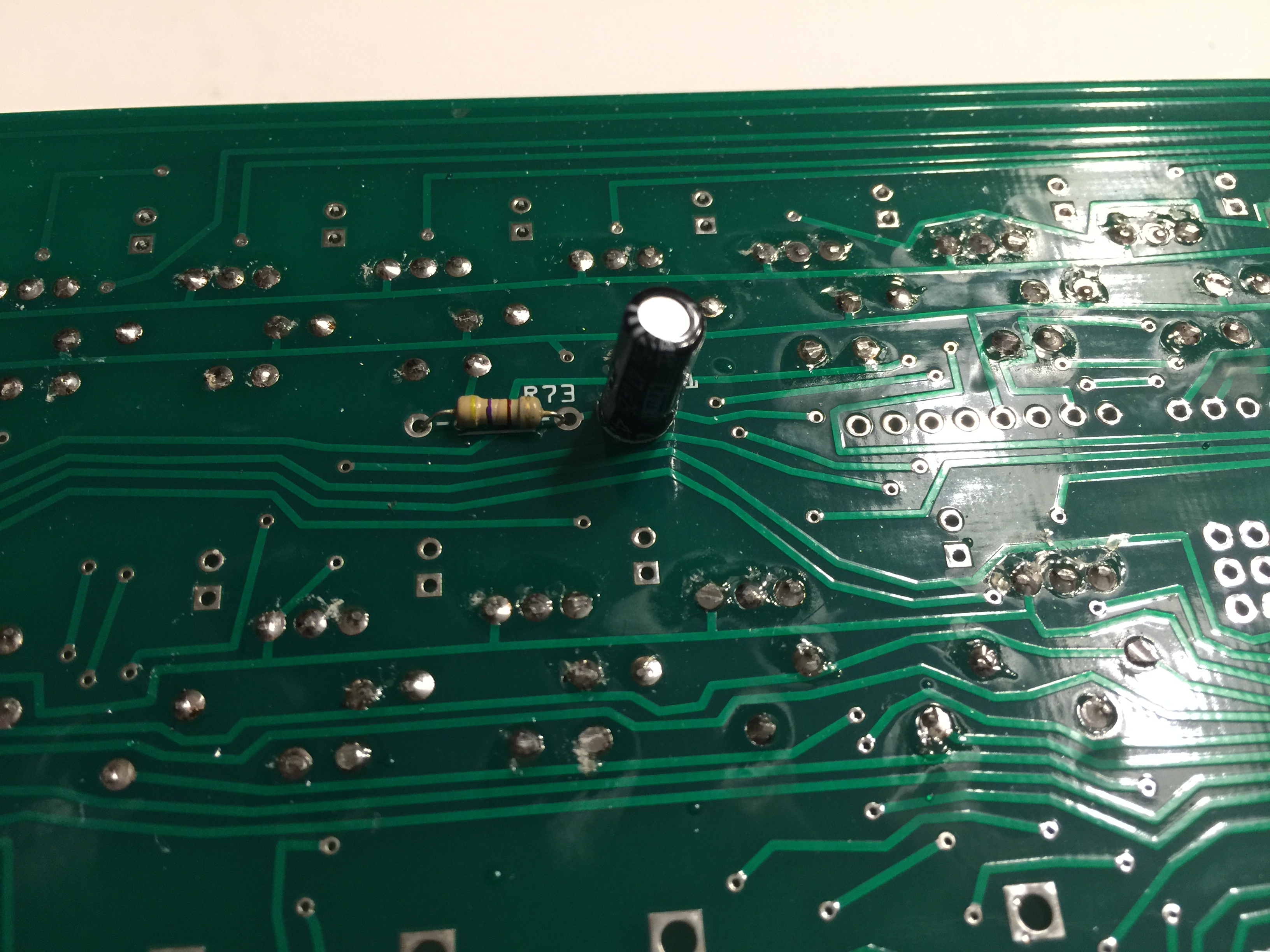
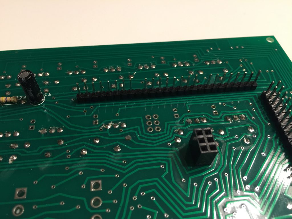
These two components mount in the back (underside) of the PC board in R73 and C1. The orientation of the resistor does not matter, but make sure the short lead of the capacitor (marked with a "-" on the side) goes in the hole also marked with a "-".
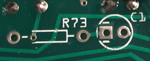 Update: Version 1.5 boards now have the markings for these components on the top of the board. You can mount them on either side, just be sure the polarity of the capacitor is correct.
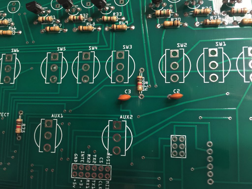
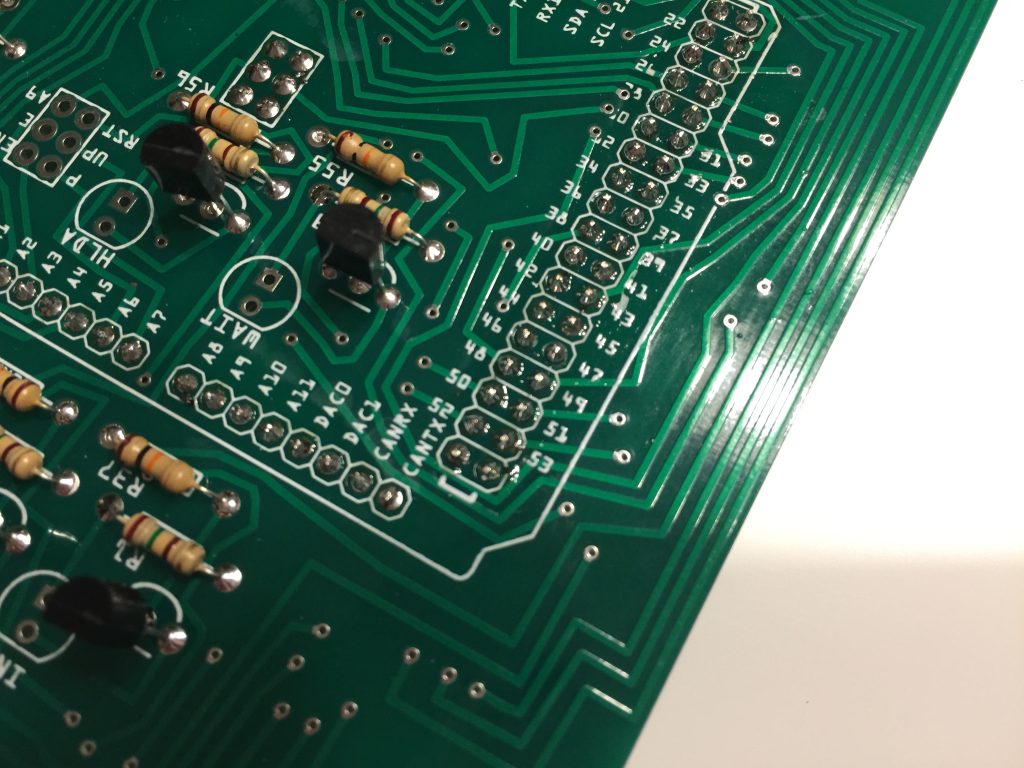
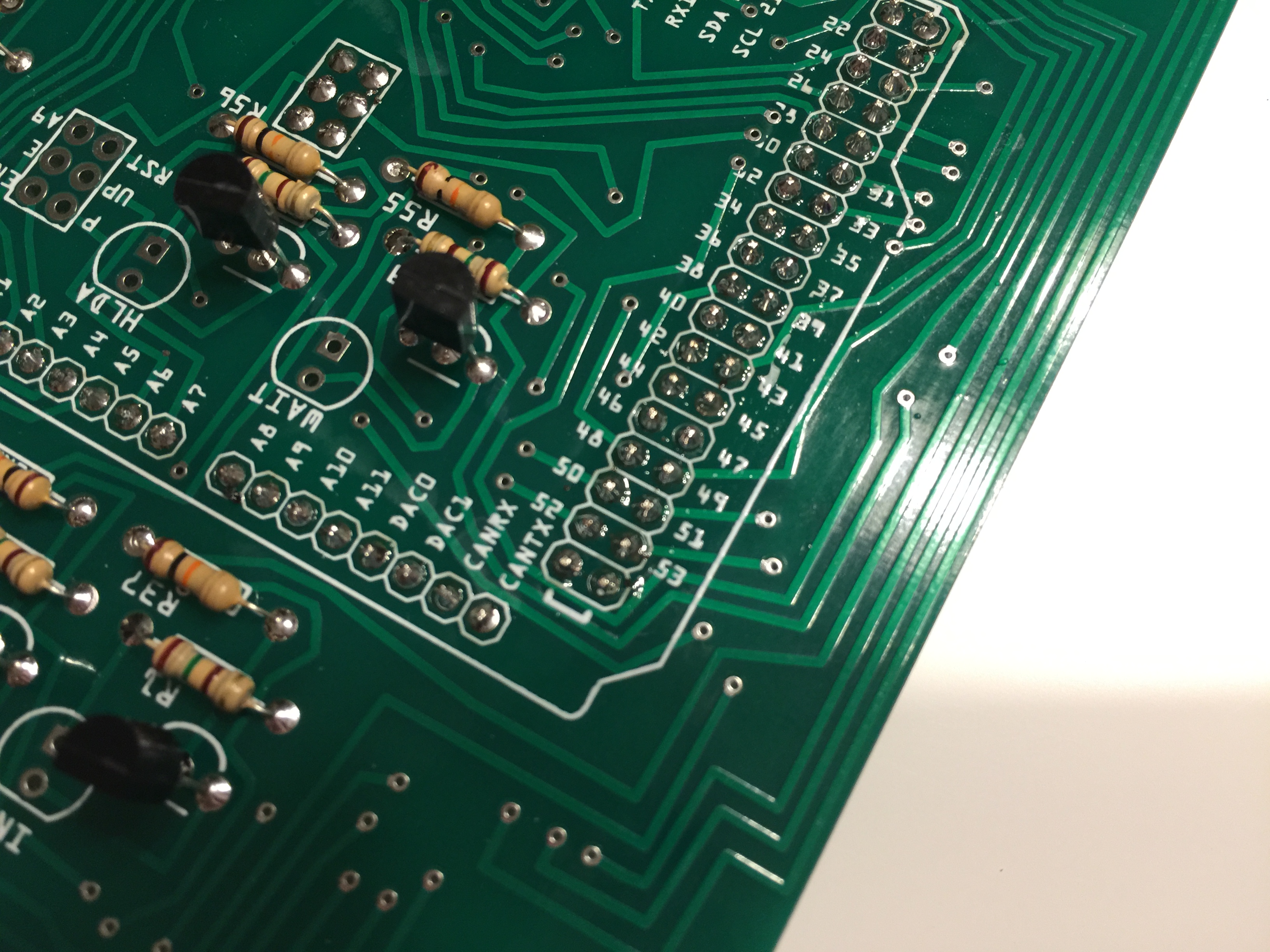
- In the same bag, you will find two 0.1 µF capacitors (marked with "104") and two 1kΩ resistors (Brown, Black, Red, Gold).

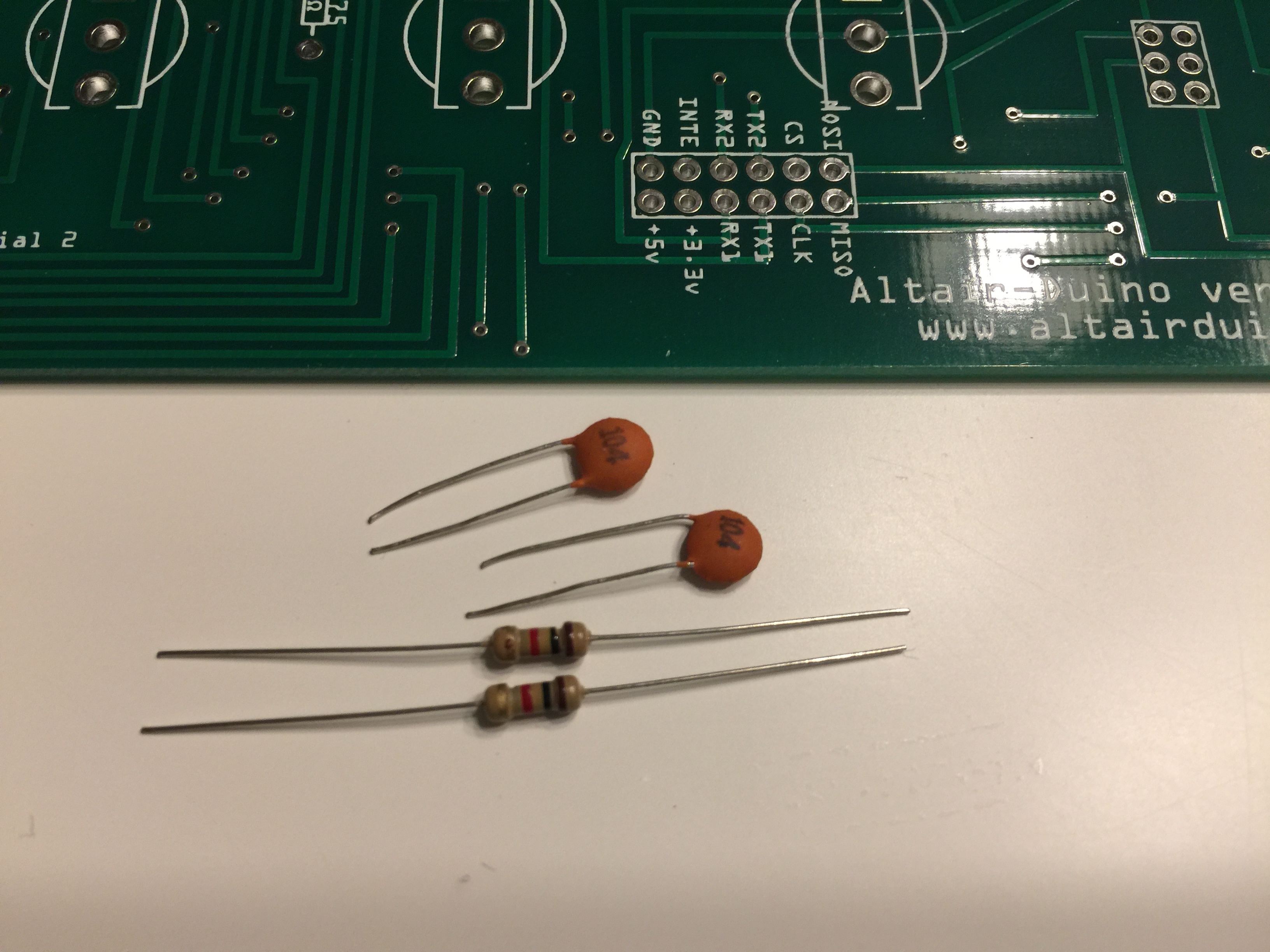
- Those can be mounted on the front of the PC board in R74, R75, C2, and C3 on the lower right side of the board. The orientation of the components does not matter.

- Use your side cutters to clip the single pin headers into 5 segments of 8 pins, and 1 segment of 10 pins to mount the Arduino board. Also clip the double header to a 36-pin (2x18 pin) header.
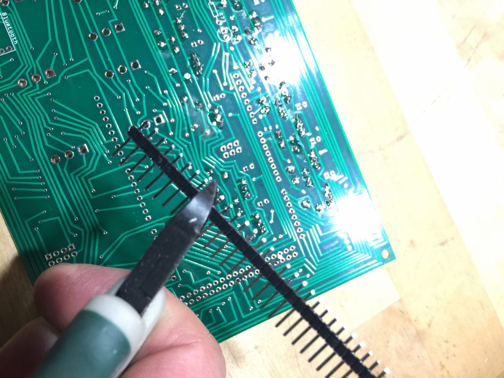
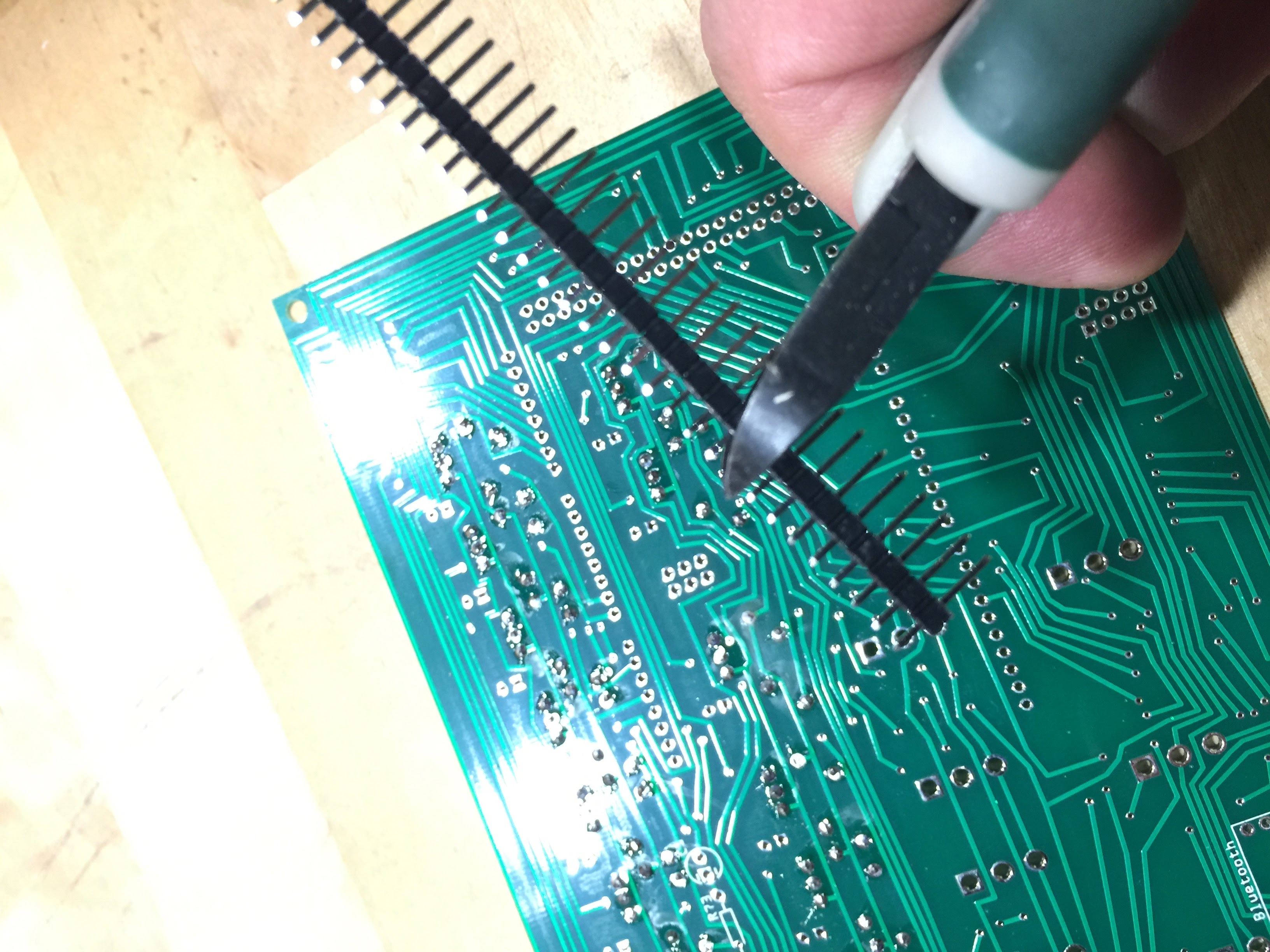
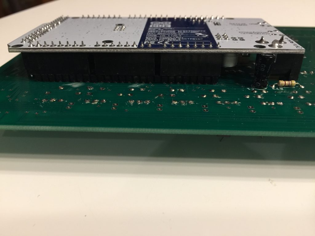
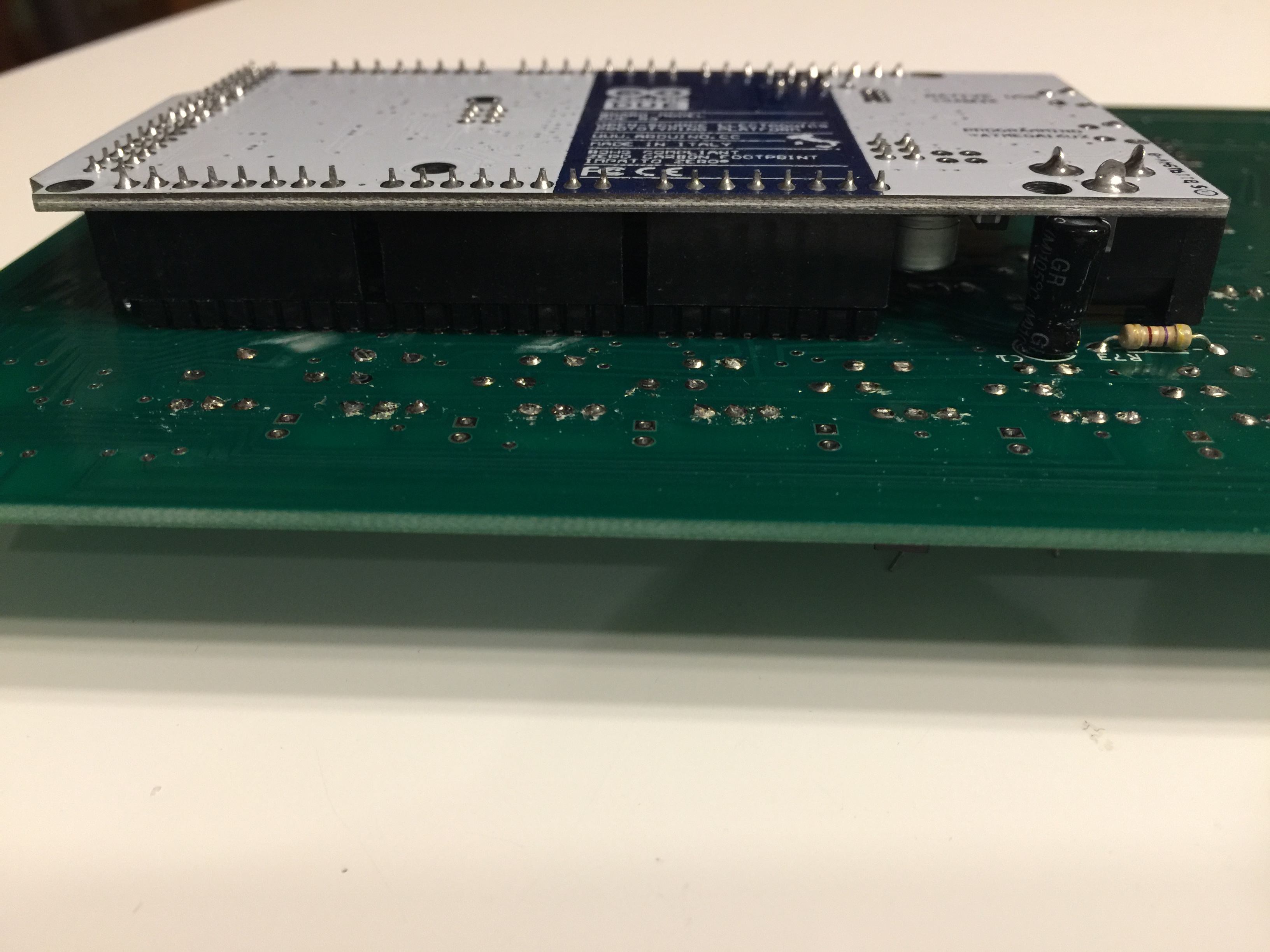
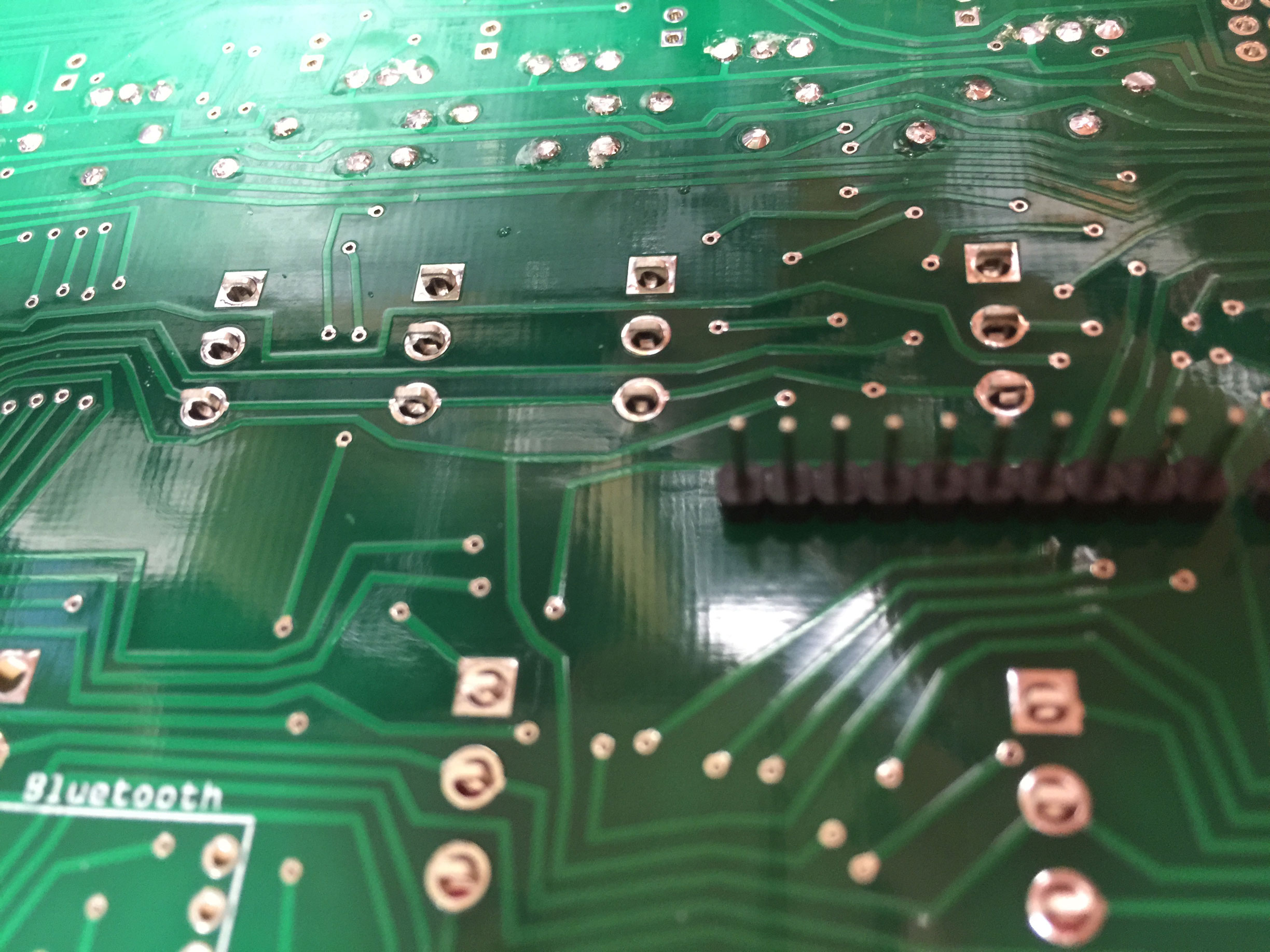
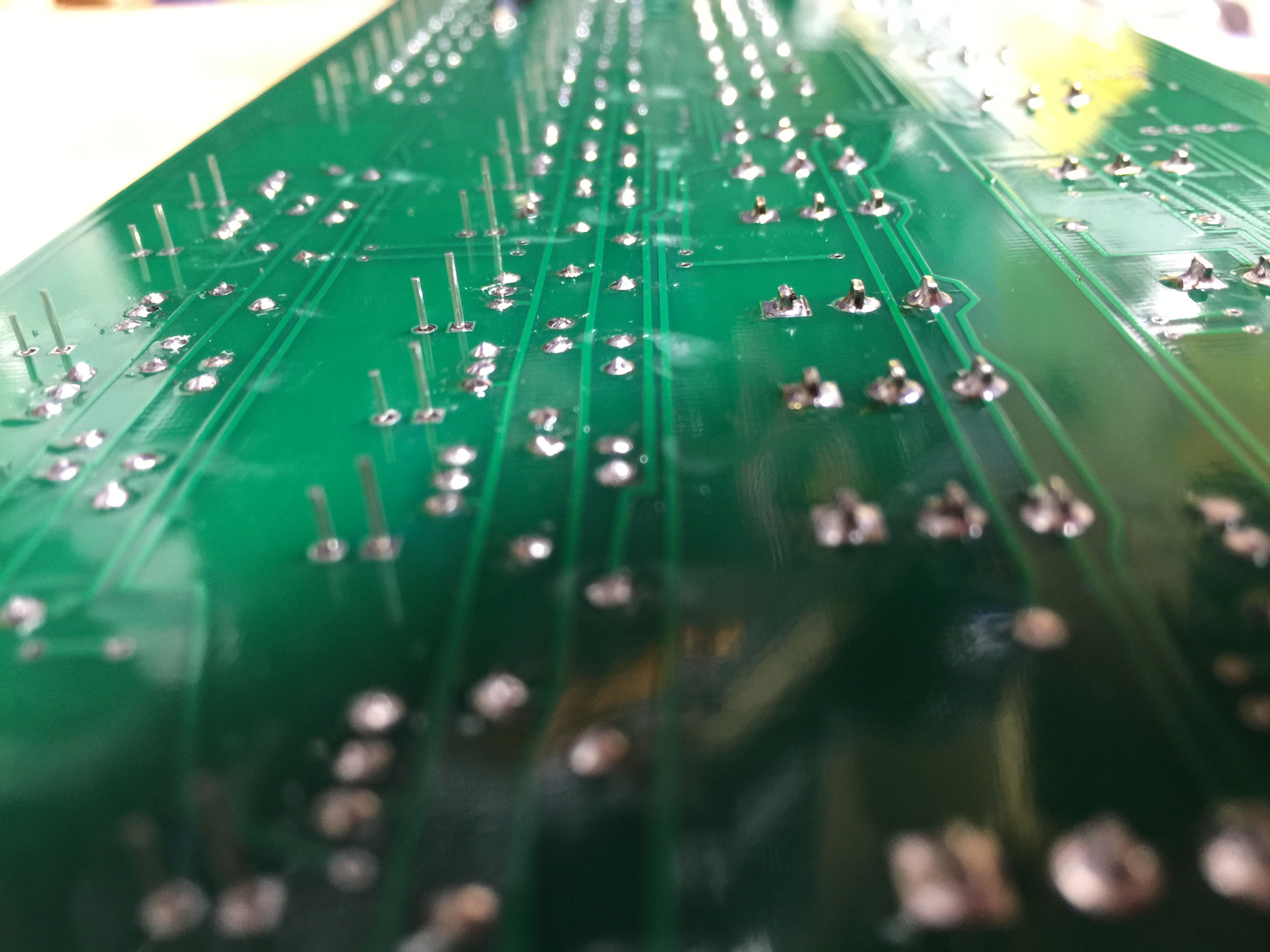
- Add the male headers to the underside of the PC board. You can also add the six-pin female header for the SPI connector on the Arduino. Make sure you add these to the correct side of the board because desoldering 92 connections would not be fun! It may be helpful to install the headers in your Arduino Due, then insert the headers in the circuit board to hold them in the correct position while soldering.

- Solder the headers carefully. Make sure they are as close to vertical as possible, and make sure the solder flows completely over the connection. Most problems happen here with cold solder joints, or solder bridges.
- After you're done soldering the headers, try putting the Arduino in place and check for a secure fit. Remove it when you're done.
- Get the bag containing 25 toggle switches (17 blue and 8 red). If your switches have nuts and washers, you may remove and discard them. Before installing the switches, I'd strongly suggest toggling each back and forth a few times to make sure they move smoothly and with the appropriate amount of effort. I recommend this because desoldering a bad switch is a real pain!
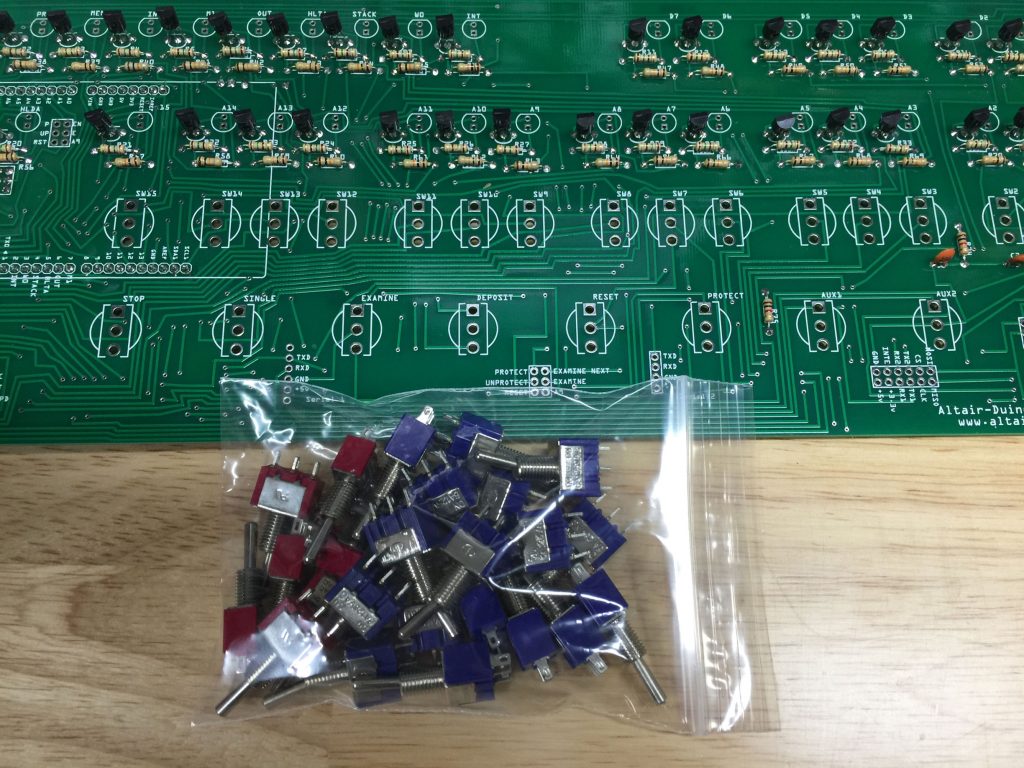
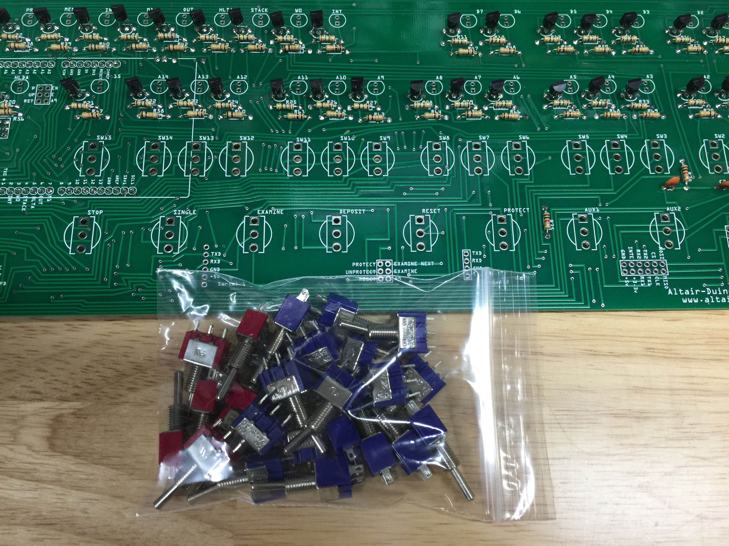
- Put all the switches in place without soldering them. Blue (two position) on the top row and the power switch location, Red (three position momentary) on the bottom row.
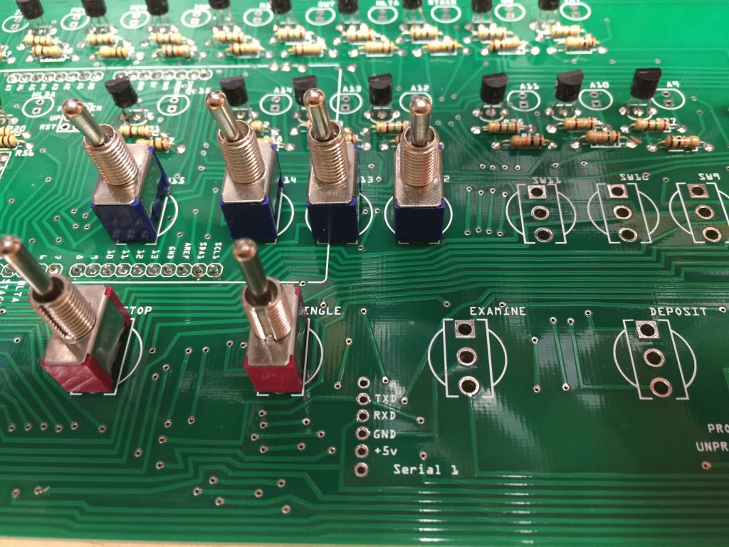

- Put the front panel in place to hold the switches in the correct position (having all two-way switches in the down position makes this easier.)
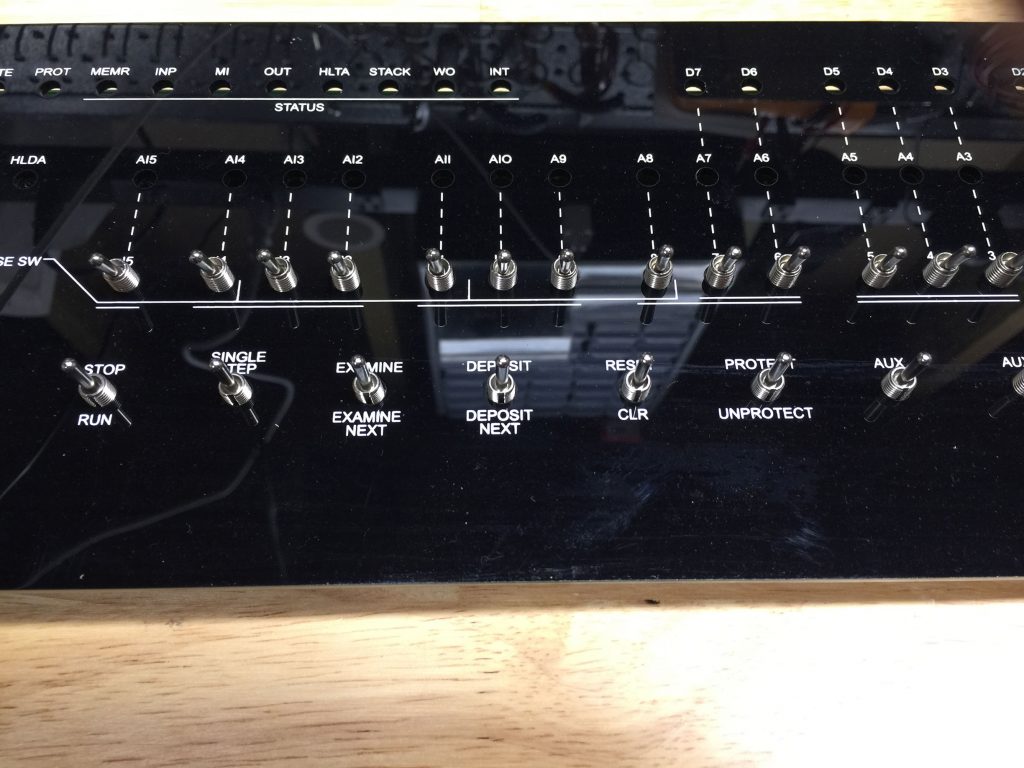
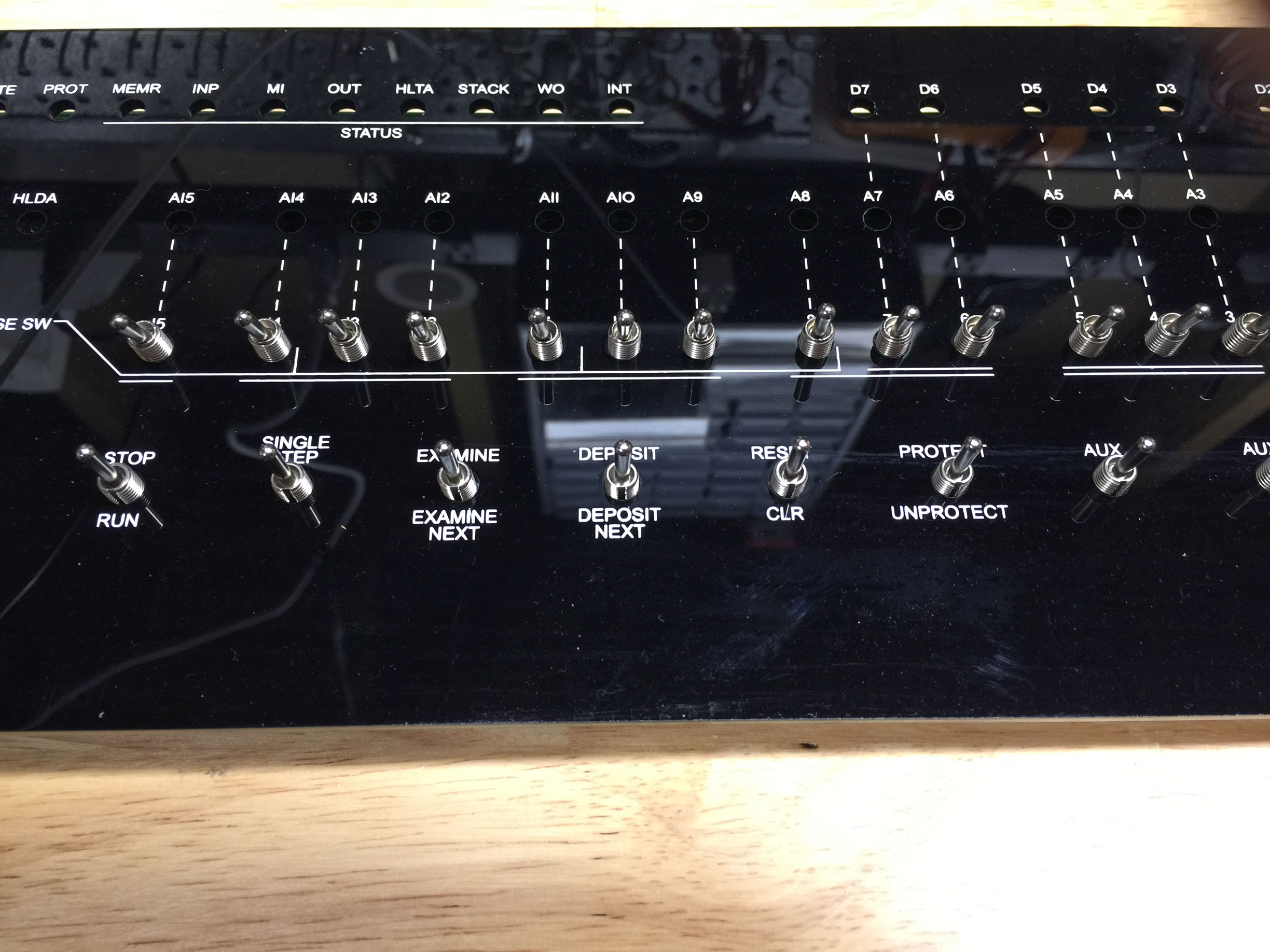
- Turn the board over and solder the switches. HINT: Before you solder, make sure all three legs are protruding through the holes. Two isolated incidents have been reported where the leg was pushed up into the switch, causing a short which was very difficult to diagnose!

- Next is the bag of LEDs and 12mm spacers.
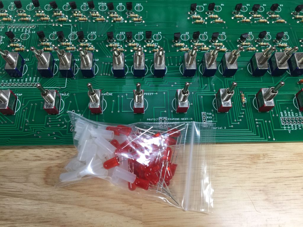

- Just like the switches, put the LEDs and spacers in place and do not solder them You do not have to do them all at once, it may be easier to do them in two or three groups. The orientation if the LEDs is crucial. Make sure the long lead of the LED is toward the bottom of the PC board and the flat side of the LED is toward the top.
- Again, like the switches, put the front panel in place to hold the LEDs while you solder them.

- While you are soldering the LEDs, you can verify that the long lead is toward the bottom of the board.

- Make sure you trim the leads after you solder the components. Next we are installing a ribbon cable that could get punctured if you leave the LED or transistor leads untrimmed. Update: Version 1.5 boards do not need this ribbon cable. If you have version 1.5, you can skip the next three steps.

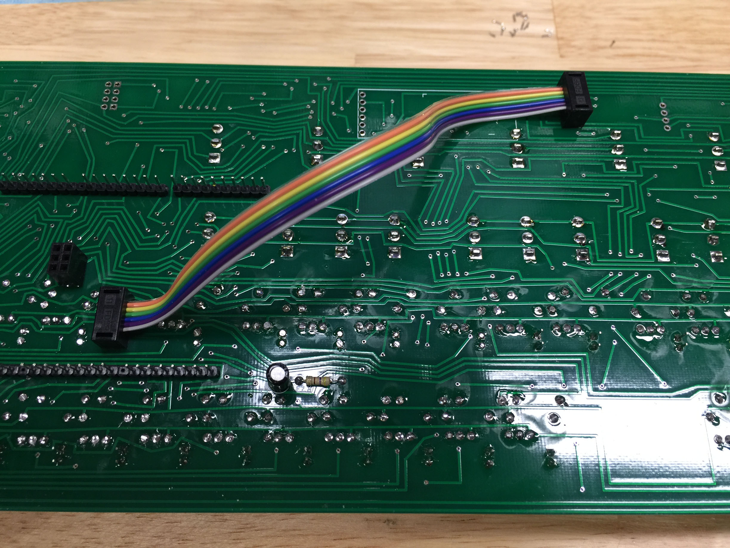
- We're going to install the six-pin ribbon cable on the underside of the PC board. On the upper side of the board, you can see the labels pictured here. Not required for version 1.5.
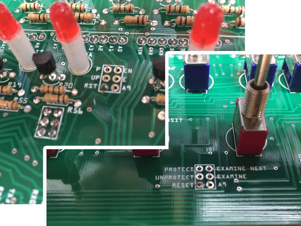

- Place the cable as pictured and solder it in place. Not required for version 1.5.

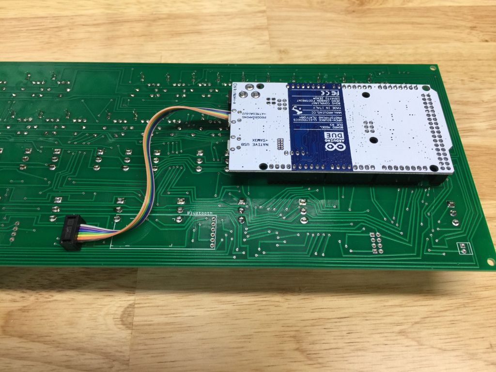
- Put the Arduino in place, routing the cable as shown. Not required for version 1.5.

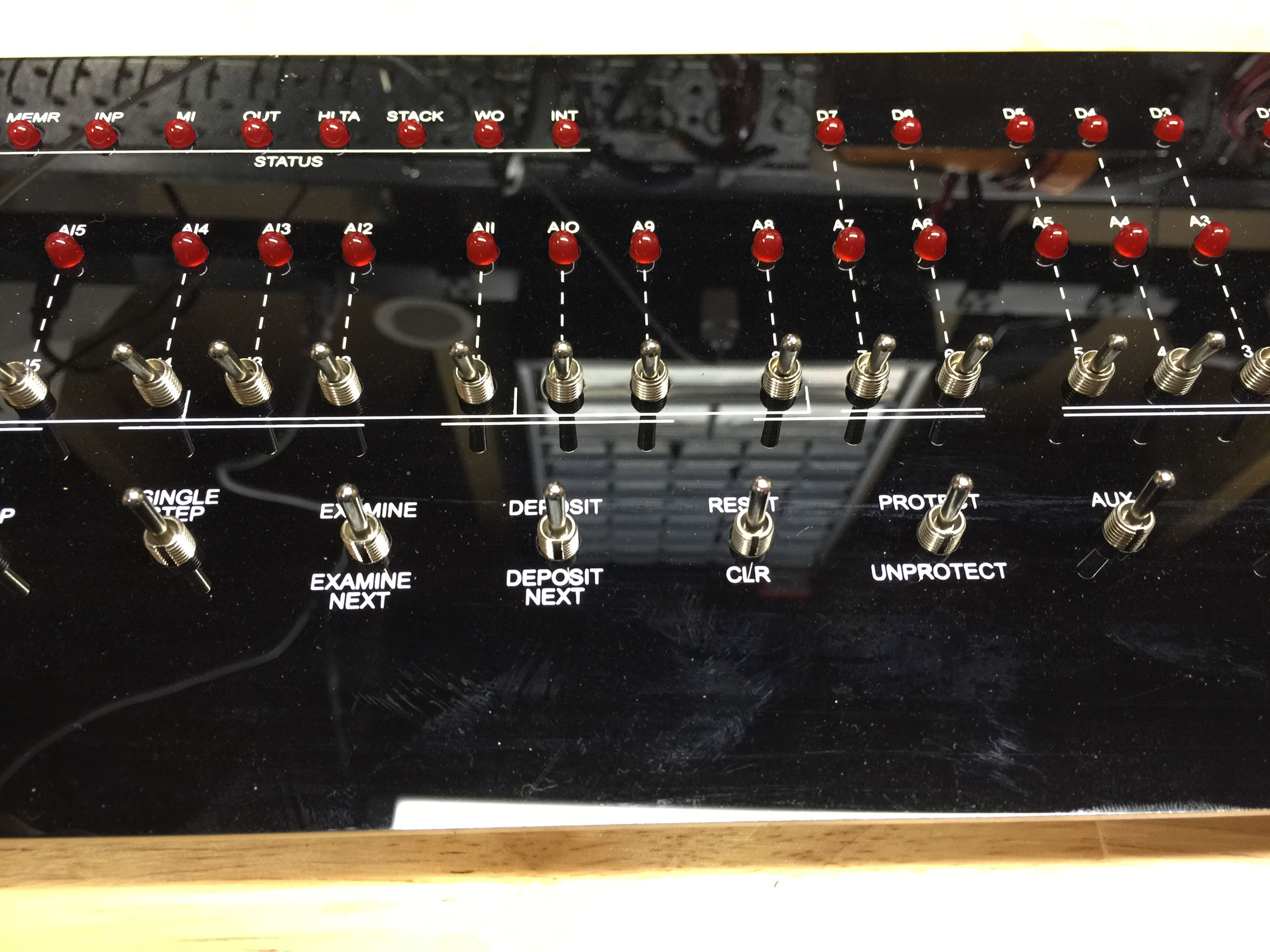
- This is a good time to test your kit so far. Take the USB cable and plug it into the Programming port on the Arduino. Turn the board over (so you're looking at the face) and plug the other end of the USB cable into a computer or USB power supply. When the kit is powered, all LEDs will briefly flash, then go dark, and a second or two later, a random pattern of LEDs will light. My favorite quick-and-easy test is to set SW1 on and lower the AUX1 switch. This will run "Kill The Bit" and you will see LED15 to LED8 light in sequence.
- Here's a good second test: set all address switches (blue switches) to ON and raise the EXAMINE toggle. All address LEDs (0-15) should light. If not, there is either a problem with that addresses LED or toggle switch.
- Add the 14mm male/female standoffs on the top, and two 20mm male/female standoffs on the side with the Arduino.
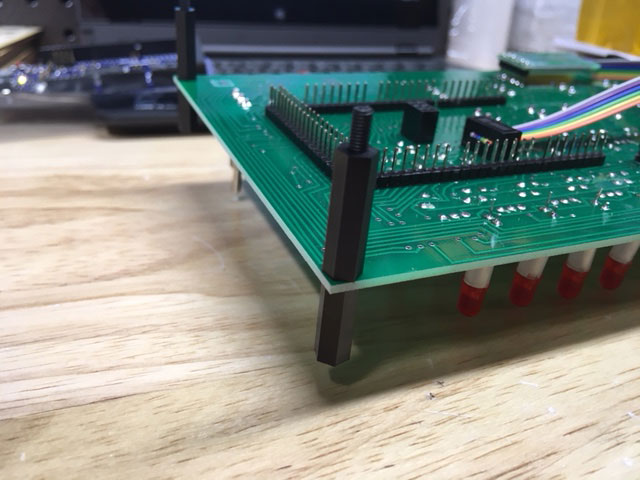
- On the other side add the 14mm male/female standoffs on the top, and two 20mm female/female standoffs on the bottom.

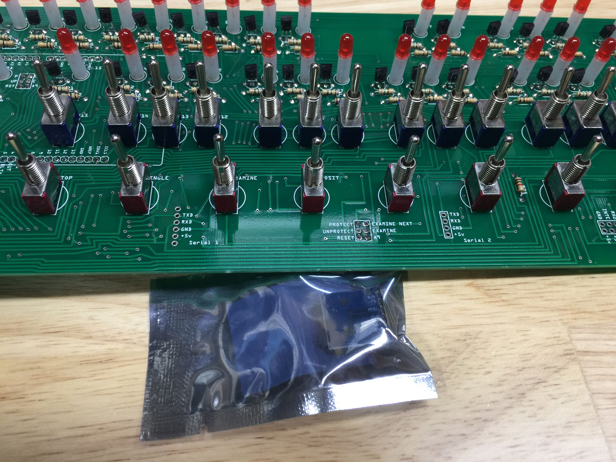
- If you will not need to access the micro SD card, the SD card module is installed on the back of the PC board where indicated. (There are very good tools included in the Altairduino for uploading to the SD card.)

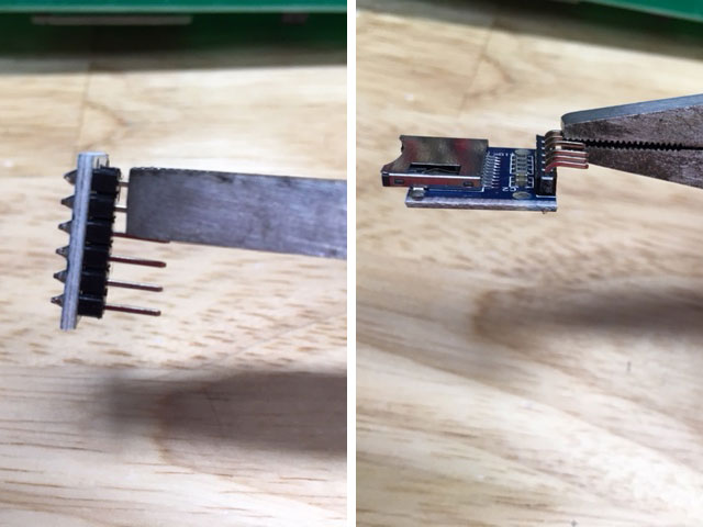
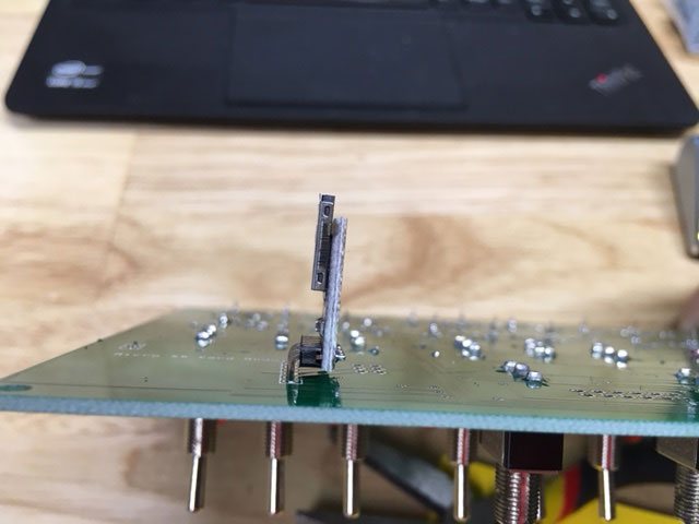
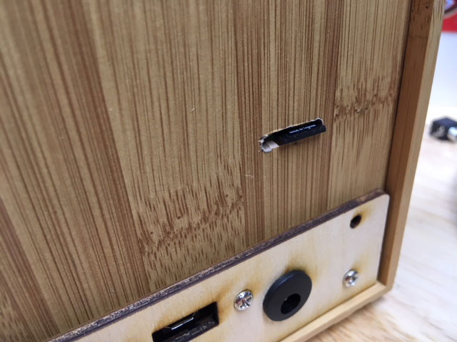
- If you would like the micro SD card accessible from outside the case, take a needle-nose pliers and carefully bend the pins to a 90 degree orientation.
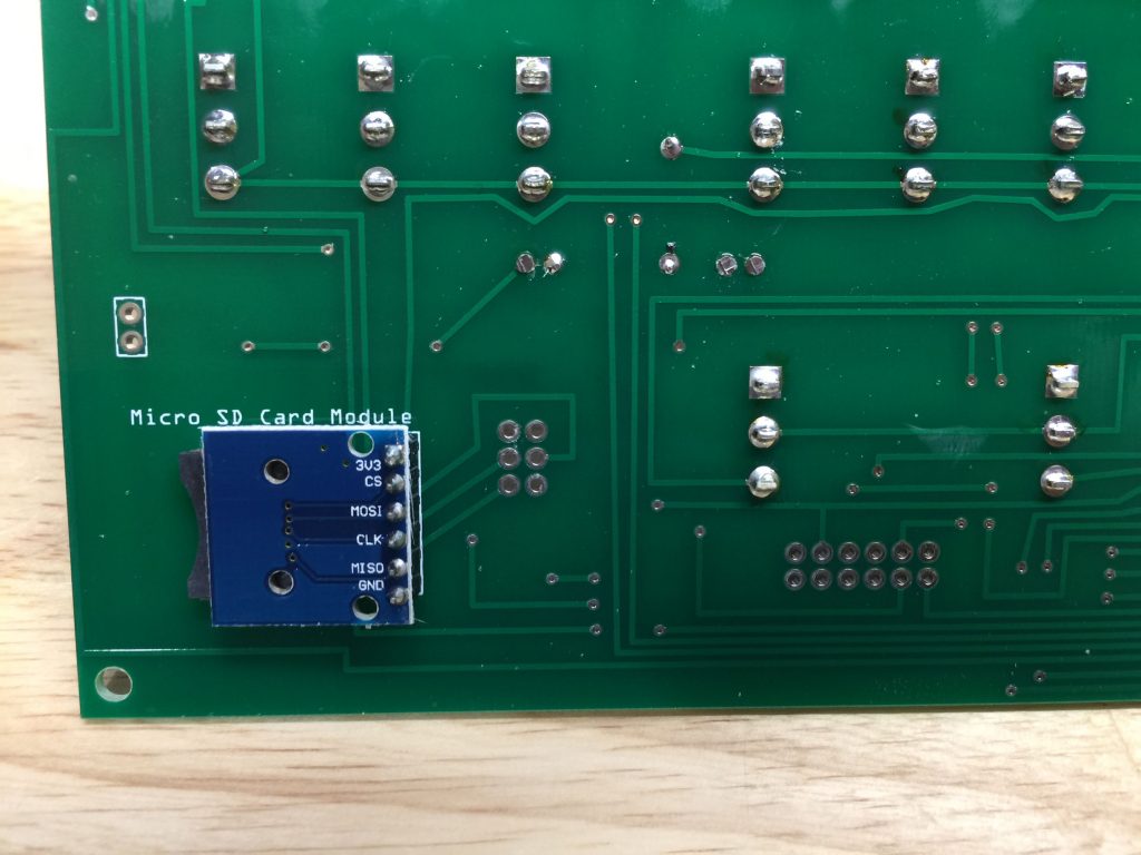
- Install the module with the SD card holder facing toward the outside of the PC board, as shown. Make sure it is perpendicular and square with the PC board. There is a hole in the bamboo case for access, the end of this module will fit through that hole.
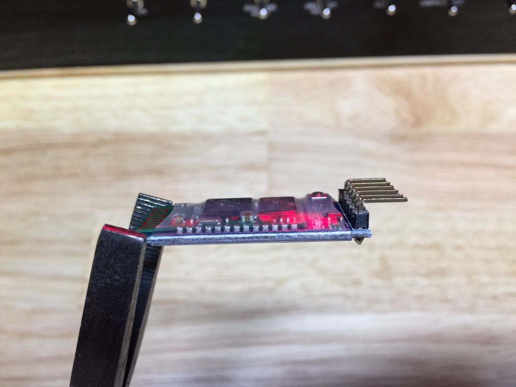
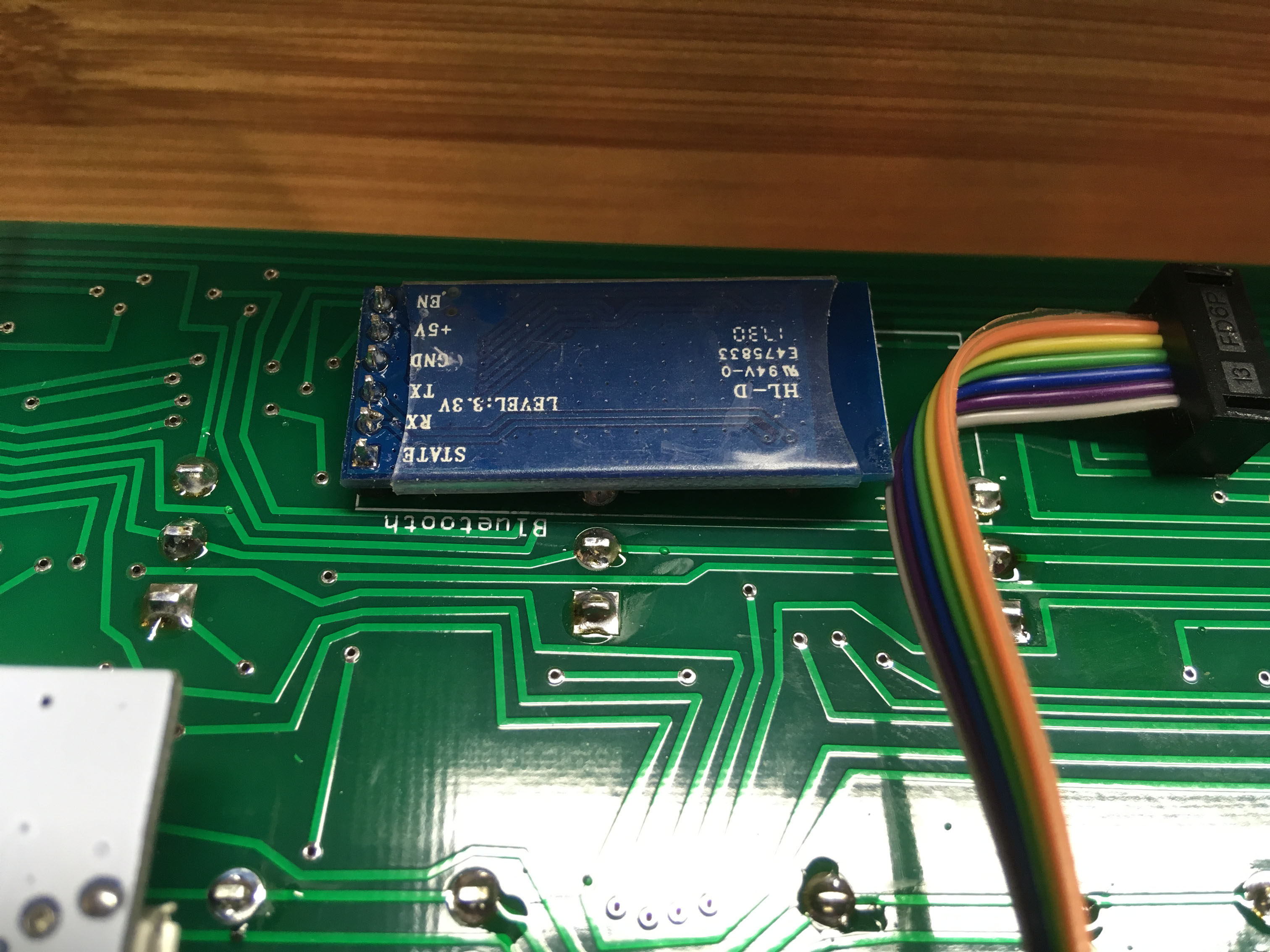
- Next we're going to add the Bluetooth module. If your module has angled pins, that's not quite what we want.

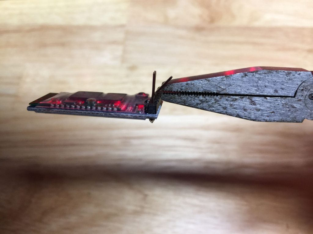
- So grab a needlenose pliers and bend the pins straight slowly and gently.

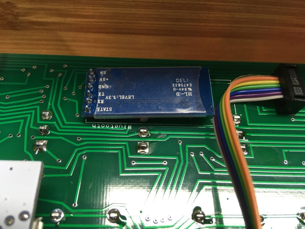
- You can now solder the Bluetooth module to the underside of the PC board. Your Bluetooth module may have six pins or four pins. If it only has four pins - solder them to the center four pins of the six-pin connection area.
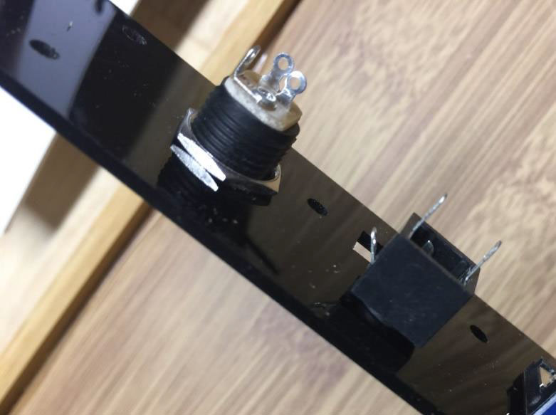
- Now you will mount the components in the rear panel. Start by placing the DC power jack and tighten the nut. Follow that by installing the audio jack and carefully tightening the nut. (I have found if the audio jack nut feels loose, apply a bit of solder to the nut after installing.)
- Remove the standoff hex nuts from the MAX3232 serial module.
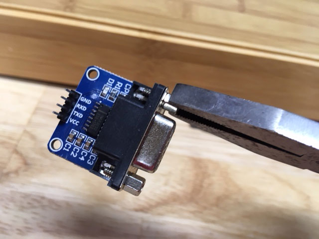
- The standoff hex nuts will secure the module to the rear panel.
- Next you will mount the USB panel extension. The extension mounts to the rear panel with two 8mm steel screws.
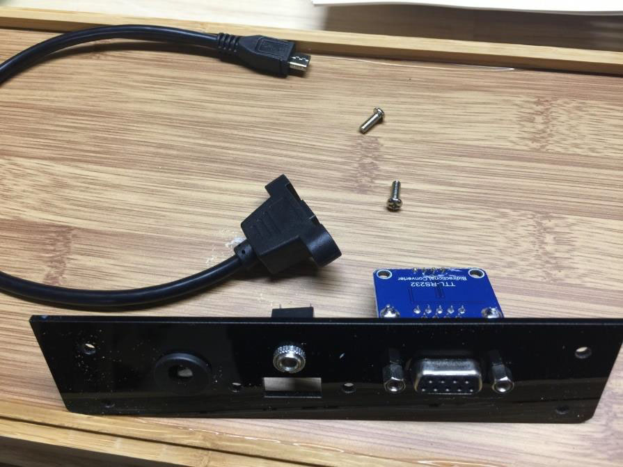
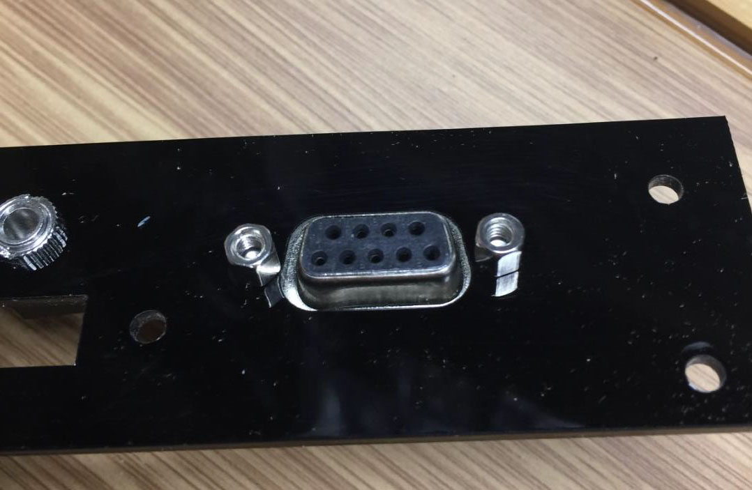
- Here is the finished rear panel.
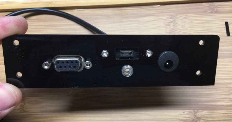
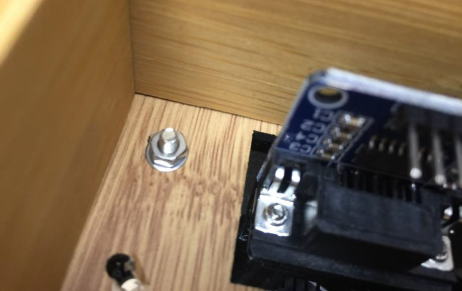
- Attach it in place to the bamboo case with the outside two screws only (with washers and nuts.)
- Solder a pair of wires at least 35cm long to the power jack. Note the polarity in the photo.
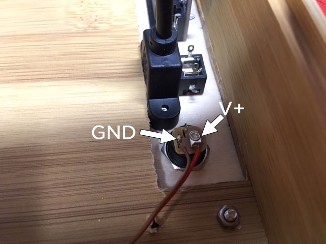
- Solder the other ends to the power input on the opposite side of the PC board. Make sure there are no shorts, and that you don't reverse the polarity.

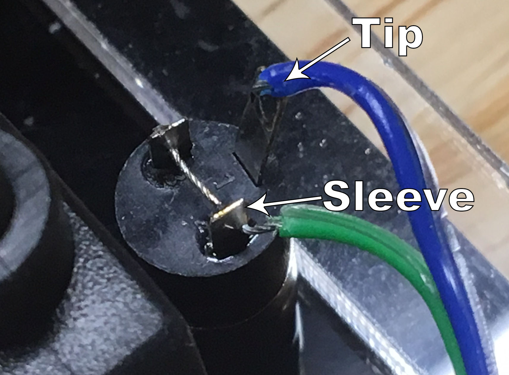
- Here are the connections for the audio jack.
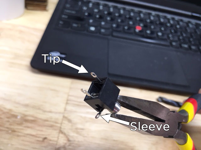
- If your kit came with a round audio jack like this, here are your connections:

- Wire the sleeve connection through both pins 2 and 3 on the round connector.
- Audio jack connects to the opposite side of the PC board as the power connections.
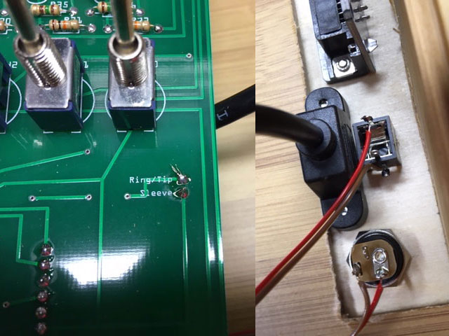
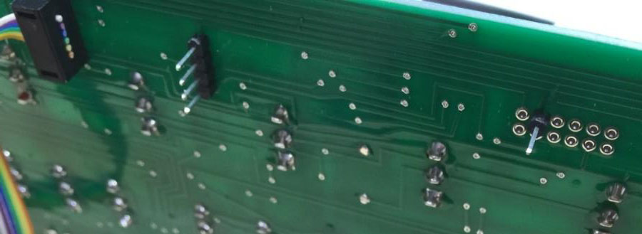
- Next, we connect the serial port module to the PC board. You should have part of the Arduino header left over, so solder a four pin segment to the underside of the PC board - this is where the cable will plug in. The pins are labeled on the top of the PC board and on the serial module. If you have version 1.4 of the PC board: We are also going to take power from the "expansion connector" to the right of the serial connections. This is because we want a 3.3v power supply for the serial module, not 5v. Notice the single pin soldered on the right side of the photo. If you have version 1.5, the power connector on the serial port connection is 3.3v.
- Please note: this is not a "straight through" connection. Make sure the matching labels are connected properly: Version 1.4: VCC -> VCC, GND -> GND, RXD -> RXD, TXD -> TXD Version 1.5: VCC -> VCC, GND -> GND, TXD -> RXD, RXD -> TXD)

- Connect the USB extension to the programming port on the Arduino.
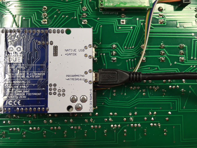
- It's time to put the completed circuit board into the case. You will have to gently push down the connector for the serial module to slightly bend down the pins. Also note the orientation of the USB extension cable, this will keep it out of the way of the PC board.

- If you put the SD card in before you do the final assembly, it will help you guide the SD module into place in the slot you cut in the case.
HINT: If you have loaded the disk images on the card and see nothing but a non-stop sequence of “c” when you access the card, you need to completely reformat the card (FAT or FAT32, be sure to select FULL format, not a quick format.)
Better yet, I strongly suggest downloading the SD card formatter from the SD Association.
I have have built dozens of Altair-Duinos and every time the SD card functions correctly, but I have run into a couple circumstances where the micro SD card I was trying to use *absolutely* would not work. I have found that the SD module used in this kit will only read/write "SD2" cards, and not "SD1" cards. I have no idea what the difference is. A few guys have reported that reloading the Arduino software has helped them.
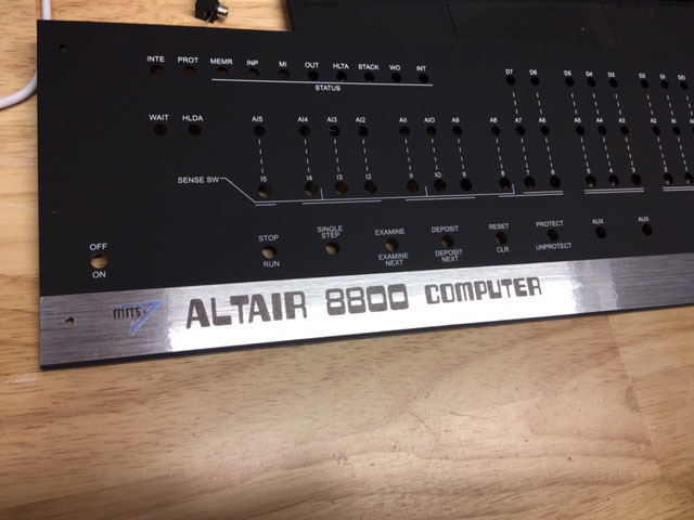
- Apply the Altair 8800 sticker to the front panel. The adhesive is forgiving, so if you place it wrong, you can pull it up and put it in place again. Use a small Phillips screwdriver or awl to poke holes where the bolts will go.
- Put the front panel in place and push down around the LEDs and switches to set it properly (the threaded toggle bushings should extend a few millimeters above the surface of the front panel), the panel is flexible so you can apply a bit of pressure. Then add the 10mm nylon bolts.

If your case seems a little tight (it’s wood so it tends to expand/contract with temperature and humidity) you can easily trim it a bit with an X-Acto knife.
CONGRATULATIONS! YOUR ALTAIR 8800 IS COMPLETE!